Behind the Pretty Frames: Death Stranding
- Introduction
- Configs
- Behind the Frame
- D3D12
- Compute
- Frame
- Stranding Vertex
- Copy & Clear
- Streaming Tiles Clustering [Compute]
- Streaming Priority [Compute]
- Streaming Check Activation [Compute]
- World Data Probe Texture Copy [Compute]
- Particles Update [Compute]
- Force Field [Compute]
- Force Field to Texture [Compute]
- Image Blend [Compute]
- Linear Buffer [Compute]
- Plant Compute [Compute]
- Copy & Clear
- Clear Depth Stencil View
- Snow/Mud Top View Depth Pass
- Snow Interaction Update [Compute]
- Copy & Clear
- Cloud Density
- Precipition Occlusion Height
- Copy & Clear
- Atmospheric Scattering
- Sky Dome Irradiance Contribution [Compute]
- Weather Stuff [Compute]
- Copy & Clear
- GBuffer/Deferred
- Occlusion [Compute]
- Depth Downsample
- Copy & Clear
- GBuffer Downsample [Compute]
- Prepare Lookup Texture [Compute]
- SSAO
- Copy & Clear
- Shadow Caster Height Field (Sun Shadowmap Long Distance) [Compute]
- Copy & Clear
- Indirect Forward Pass (Light Sampling)
- Copy & Clear
- Shadow Pass[es]
- Prepare Volumetric Light
- Local Light Sources
- Cloud Rendering [Compute]
- Direct Light & Sun Shadows
- Volumetric Light [Compute]
- Volumetric Clouds
- Volumetric Clouds [Compute]
- Water [Not Always]
- Prepare Cubemap 3D Texture [Compute]
- Reflection Texture
- Copy & Clear
- Diffuse Light
- Character Shading
- Eye Shadows + Tears
- Prepare for Sky Shading
- Downscale Diffuse Light
- Sky & Volumetric Fog
- Hair Mask
- Copy & Clear
- Forward Pass[es]
- Motion Vector Texture Create
- Finalize Depth Blend Texture
- GPU Particles
- Downscale Scene Texture
- Motion Blur
- DOF’s CoC Prepare [Not Always]
- Particle Based Flares (aka “Flares” or “Lens Flares”)
- Post-Processing
- Copy & Clear
- UI [Not Always]
- HDR + TAA
- UI Composite + Post Processing [Not Always]
- Present
- Life of a Frame [Rendering Graph]
- Engine General Observations
- Epilogue
- Related Readings & Videos
By the time this article published & you are able to access, it means it’s been 4-5 months as a draft since i started writing this line mid-June 2022.
Introduction
Digging games to learn about their technology is one cool old hobby that i do enjoy. But unfortunately due to the limited time & the huge effort digging-and-understanding takes (not to mention if it’s going to end in article like this) in addition to the endless catalogue of games every year, i’ve to be very very carful about my choices, even if i’ll dig it for myself without spitting a word about it. The games i usually dig, are games that i personally enjoyed playing or are from the top of my list. There are other games that are neither under my favorite genre, nor i like or enjoyed, but i do dig them because of the technology (aka engine) powering them, and today’s game is under that later category.
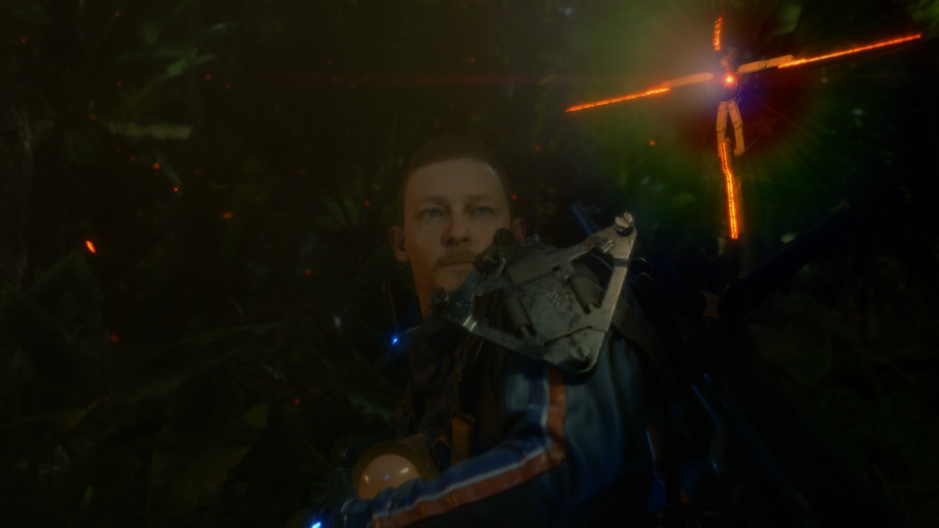
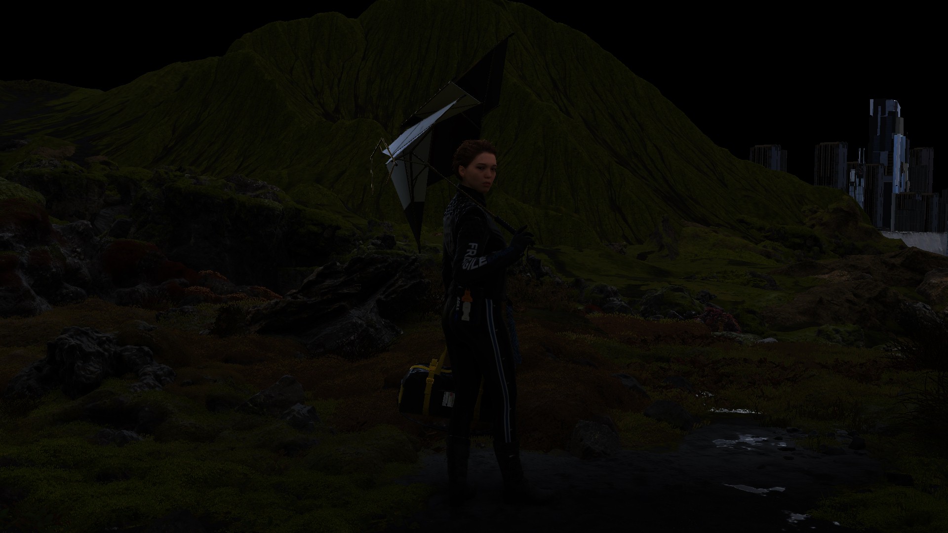
To be honest & fair, the only thing i liked about Death Stranding (hereafter referred to as DS sometimes) for long time (pre-release), was that it starring Norman & Mads, which are two of the actors i’ve enjoyed their previous works (specially TWD & Hannibal), but not because it’s a Kojima game, this is out of question! One interesting thing about any Kojima game, it is usually relying on a good & solid tech, which is something interests me more than the game itself! (again, Kojima’s quality of gameplay/story is out of question).
The main reason behind this time’s dig, was not the love of the game, or even the creator behind it, in fact i’m one of that party who found DS a little boring & didn’t catch me to beat it ASAP. But the reason here is more of a personal interest and curiosity! When you ask me “What are the engines interests you?”, you will end up with a nice handful list that is a mixed bag of RAGE, Northlight, Glacier, Anvil, Snowdrop, Voyager, Dunia, id, Frostbite…and oh boy….Decima…
Totally Not Important Engines Note
Those are the engines that have names, others that i can’t name are like Naughtdog’s, Santamonica’s, Forza’s, Insomniac’s, Detroit’s, Ghost of Tsushima’s, The Last Guardian’s, Bluepoint’s,…and the list goes on..(Unreal defiantly is not & will never be in that list…sorry for the disappointment!)
So, just to be clear, i’m not digging DS because of any deep love, neither to the game nor to the designers behind it…nope…it’s because it is the “most recent” PC game that is running on Decima..i would have gone with one from the original engine creators “Guerrilla”, but Horizon 1 on PC is fairly old comparing to DS, and Horizon 2 won’t see the PC horizons that soon..so DS is the only good shot right now….
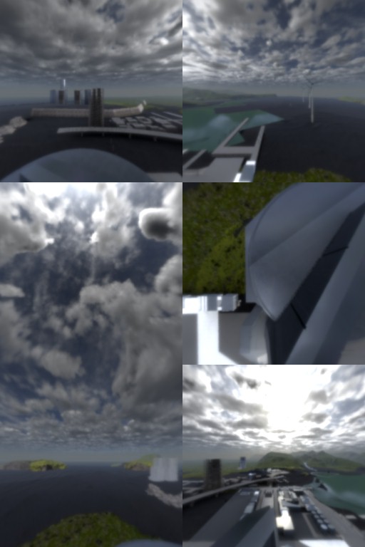
And if you’re living under a rock or not familiar at all with the name Decima in the Game Engines & Graphics space, i would like to invite you to watch this ~7 minutes presentation below (click to play), that is all about the most recent version of Decima that was used in latest Horizon game, it show case what it is capable of. This presentation was part of Siggraph 2022 Live, if you have more time, didn’t watch the live already, or curious about other showcases, you can watch the full video at Siggraph Channel here.
This downloadable video is hosted at the Guerrilla Games publications pages, if the video gone someday, poke me so i can update with another link if possible.
Configs
Once more i still captures from only one of my PCs! The PC i’m using still the same one from Elden Ring’s and Resident Evil’s studies, which is the RTX 3080, Ryzen 5950x and 32G RAM. And the graphics settings is set as the screenshot below

Despite the fact that i can use the 4k/HDR monitor that i got for Mirage engine development, but i still decided to go with 1080p & none-HDR, so i can save myself from the previous hassles with Resident Evil from large capture files, to slow process & navigation in the gpu captures, and eventually large png/jpg files to upload to the article. Plus, i don’t think there is anything interesting in 4K in Death Stranding (no super resolution for example), from 1080p to 4k felt like just a matter of more pixels!
With that said, there are very few 4k captures (5-6 or so) that i decided to take eventually, for nothing except the sake of variation and checks, those are not referenced a lot in the article (perhaps around the particles & post-processing sections), so don’t mind if you notice them few times below, i used them here and there just because it was a “clear shot” not more, but not for any 4k specific reason.
Also i did take a single HDR capture, just to demonstrate the HDR section, but apart from that single frame, everything is still none-HDR.
Behind the Frame
GIFs Note
Keep in mind, almost all gif images below are linked with 4k videos on YT. So you don’t have to narrow your eyes to see details, it was meant to make the gifs as tiny as 500px, so it don’t take much time in the page loading.
D3D12
Before starting this game, i was not aware what is the API it utilizes within the PC versions. I did play the game on the PlayStation platform before, so i didn’t care much about what was the target & status of the PC port when it came out until i started digging through it. Despite the fact that at the time i was taking the captures for Death Stranding, i was already working on yet another Sony exclusive that came to PC, and that other exclusive was ported on Vulkan, so when launched Death Stranding i thought it will be like that other game (that other game is delayed for future article), but nope, i found out that Death Stranding is using D3D12, and it seem to be utilizing the API just “fine”. i did not notice anything very special, WOW, or out of the ordinary, but at least it seem not to be taking poor & bad choices. So, i would say Death Stranding is balanced at the API utilization meter.
Compute
As i always like to give a note about compute (it’s the golden era of compute shaders anyways), it seem that compute being utilized among the frame draws pretty well, not only for post processing or particles, but, compute is heavily utilized in many other areas that is preparing for the frame or just contributing from behind the scenes without any direct draws. Again, i love compute, & i love it when i see game/engine is heavily utilizing that. So, i guess it’s once more the time, to use that meme from the God of War & Resident Evil studies!

Yet another Game/Engine that deserves my special tier compute meme!
For a quick idea about what compute usage in a typical Decima frame of Death Stranding, i’ll leave below just the summary for the utilization in dispatch order. Full details of those usages are left at their correct order below in the Draw Section.
Compute Dispatches Queue (in execution order)
- Streaming Tiles Clustering
- Streaming Priority
- Streaming Check Activation
- World Data Probe Texture Copy
- Particles Update
- Force Field
- Force Field to Texture
- Image Blend
- Linear Buffer
- Plant Compute
- Snow Interaction Update
- Sky Dome Irradiance Contribution
- Weather Stuff
- Occlusion
- GBuffer Downsample
- Prepare Lookup Texture
- Shadow Caster Height Field (Sun Shadowmap Long Distance)
- Cloud Rendering
- Volumetric Light
- Volumetric Clouds
- Prepare Cubemap 3D Texture
- Color & Gloss Buffers
Frame
Stranding Vertex
Yet another game that got it’s own share of the vertex descriptions party. Below is not defiantly everything, there are quite more than that & i might’ve missed some. Again, it is not something that i’m a big fan of, but it is what it is. Below are the ones that i was able to spot, not sure which ones that slipped from me, but those ones are the ones that kept coming again & again on my face during those few months i spent in the journey of this breakdown
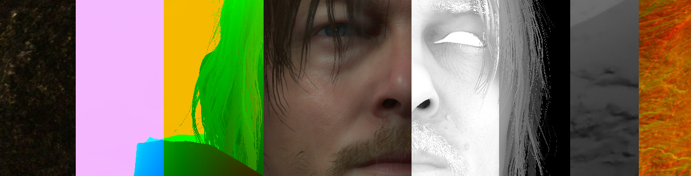
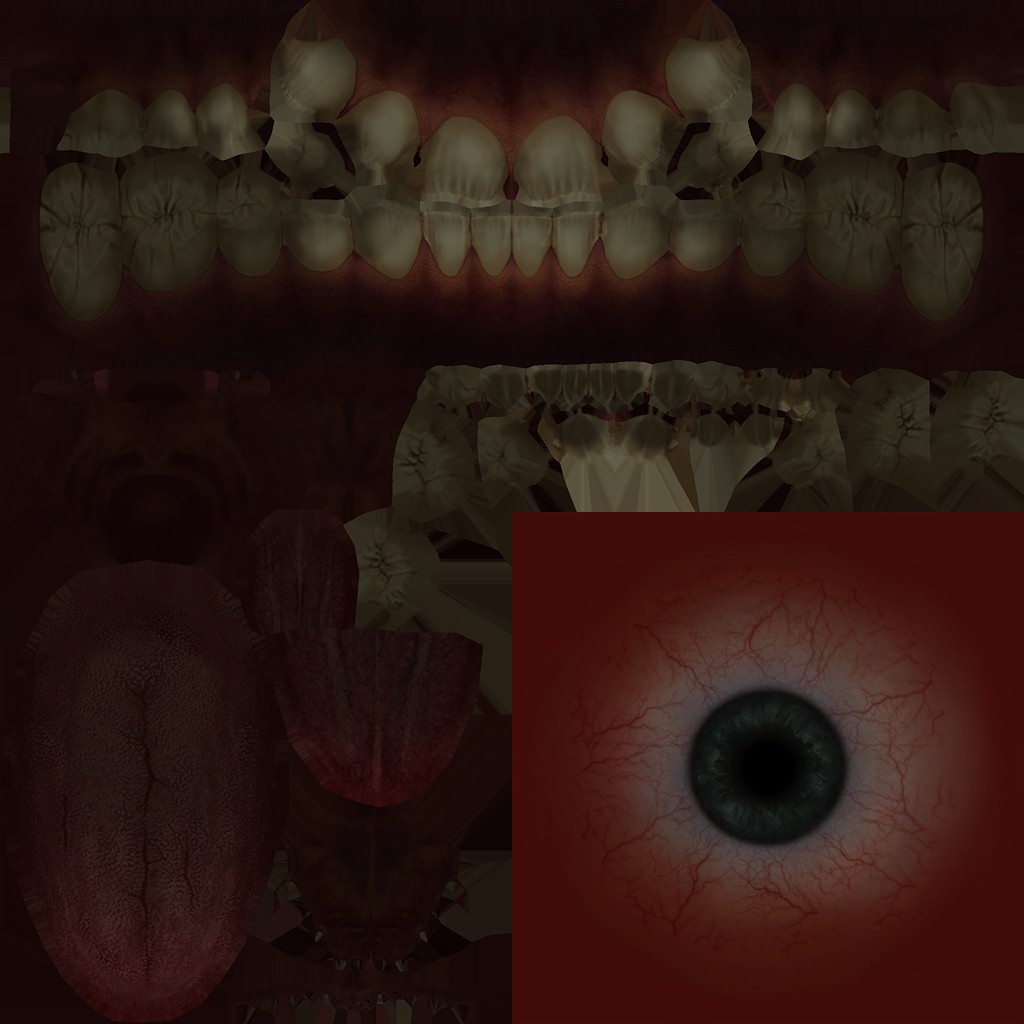
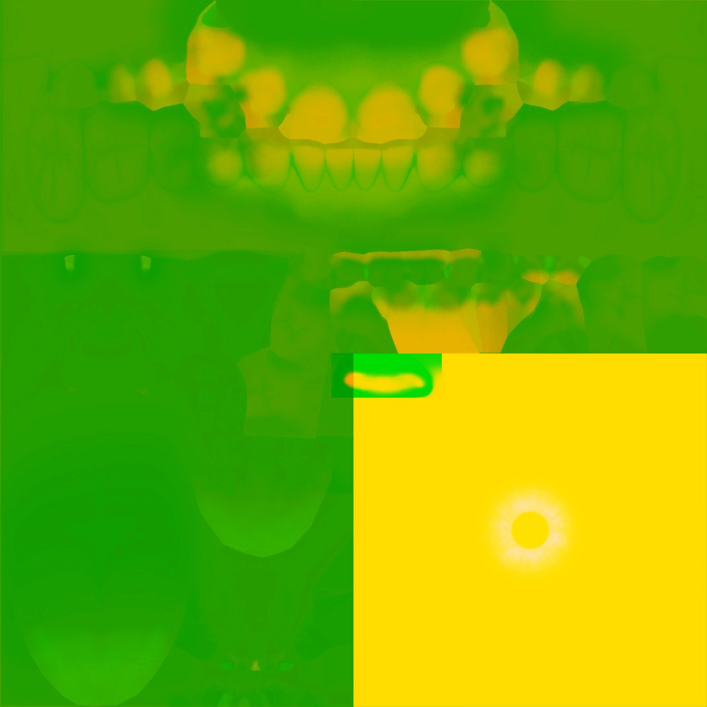
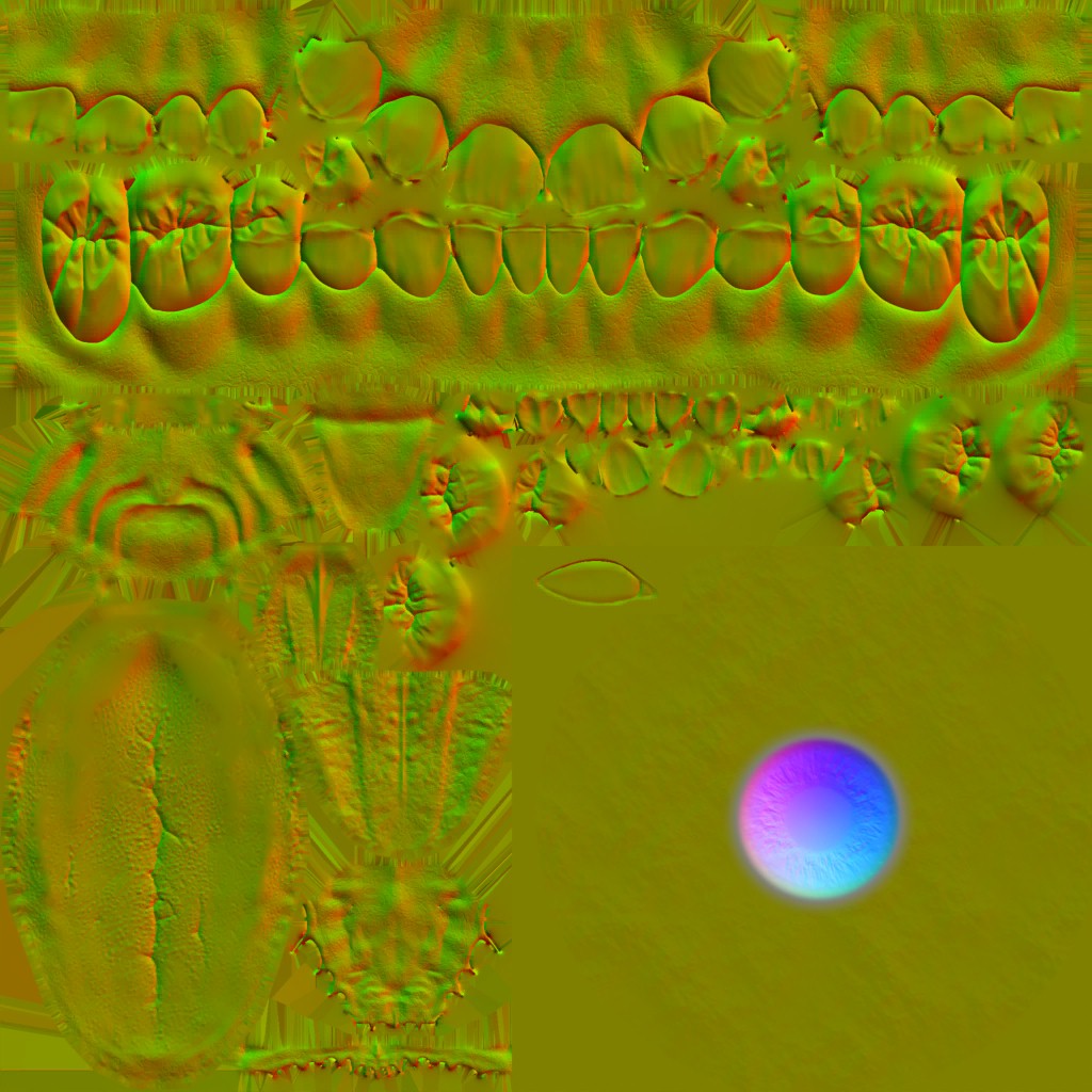
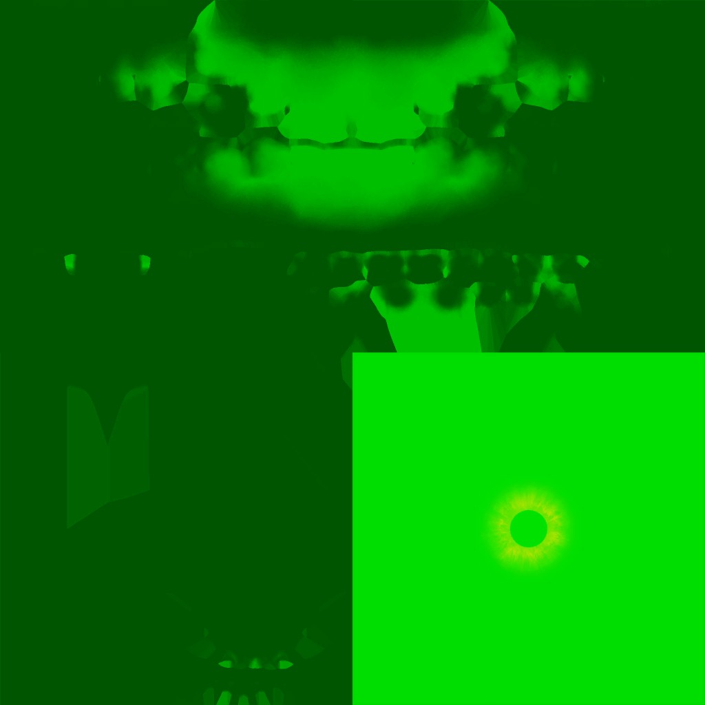
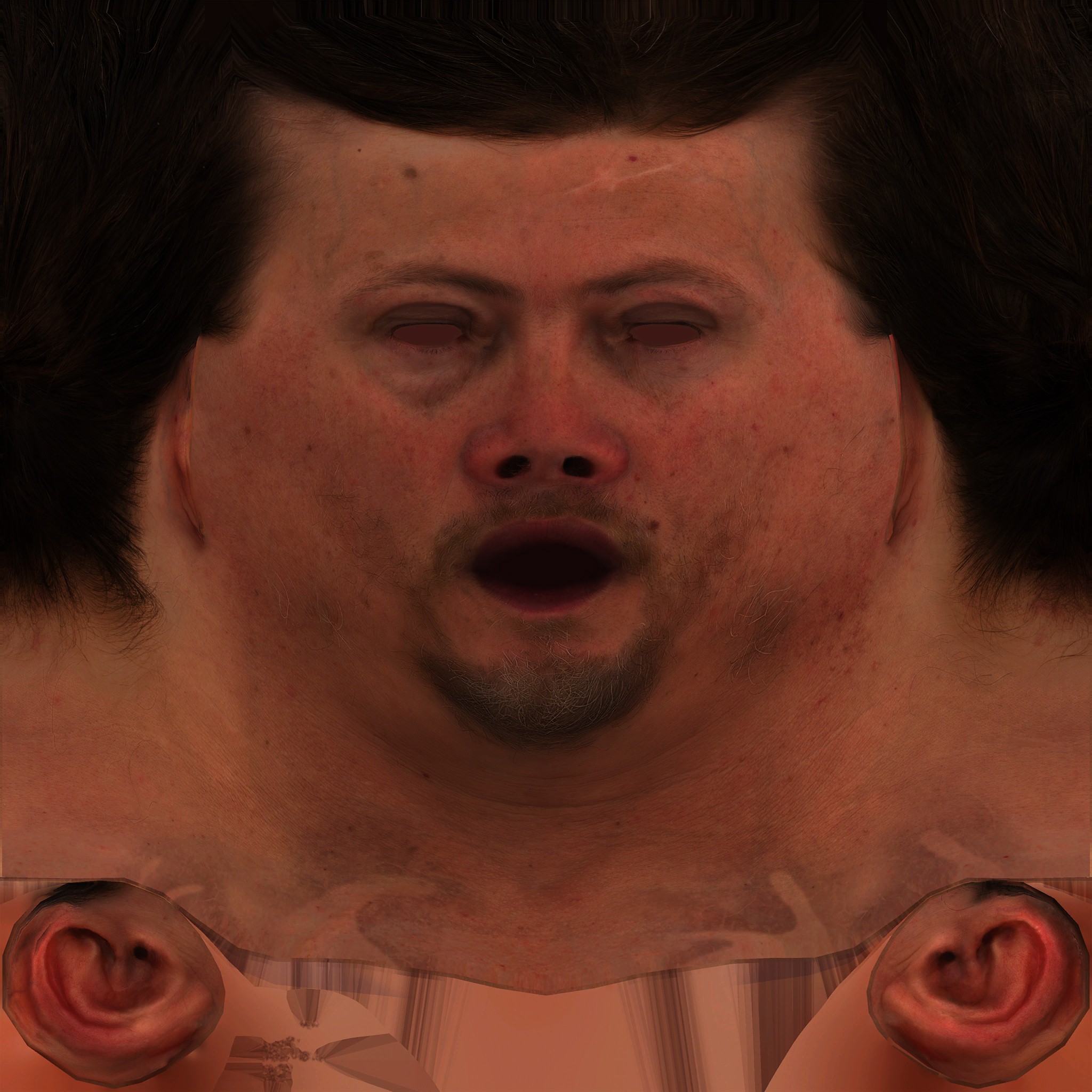
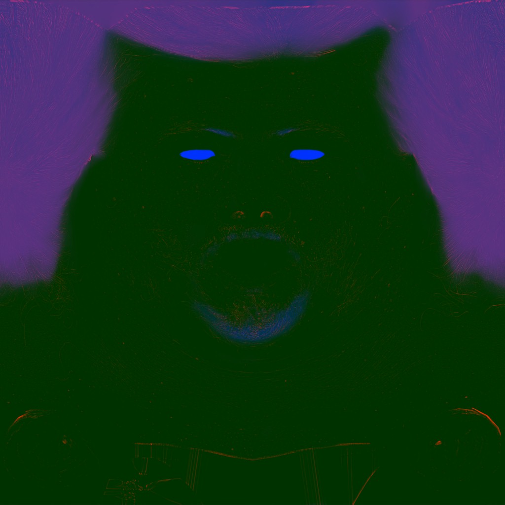
Death Stranding’s Vertex Description – Skinned Flesh (Head, Tongue, Teeth,…etc.)
POSITION         R32G32B32_FLOAT           0
BLENDINDICES     R8G8B8A8_UINT             12
BLENDINDICES     R8G8B8A8_UINT             16
BLENDWEIGHT      R8G8B8A8_UNORM            20
BLENDWEIGHT      R8G8B8A8_UNORM            24
NORMAL           R32G32B32_FLOAT           0
TANGENT_BFLIP    R32G32B32A32_FLOAT        12
COLOR            R8G8B8A8_UNORM            0
TEXCOORD         R16G16_FLOAT              4
TEXCOORD         R16G16_FLOAT              8
TEXCOORD         R16G16_FLOAT              12
Death Stranding’s Vertex Description – Skinned Hair & Clothing (Wig, Eyebrows, Eyelashes, Beards, Pants, Shirt, Jacket, Gloves, Belt,…etc.)
POSITION         R32G32B32_FLOAT           0
BLENDINDICES     R8G8B8A8_UINT             12
BLENDINDICES     R8G8B8A8_UINT             16
BLENDWEIGHT      R8G8B8A8_UNORM            20
BLENDWEIGHT      R8G8B8A8_UNORM            24
NORMAL           R32G32B32_FLOAT           0
TANGENT_BFLIP    R32G32B32A32_FLOAT        12
COLOR            R8G8B8A8_UNORM            0
TEXCOORD         R16G16_FLOAT              4
TEXCOORD         R16G16_FLOAT              8
TEXCOORD         R16G16_FLOAT              12
TEXCOORD         R16G16_FLOAT              16
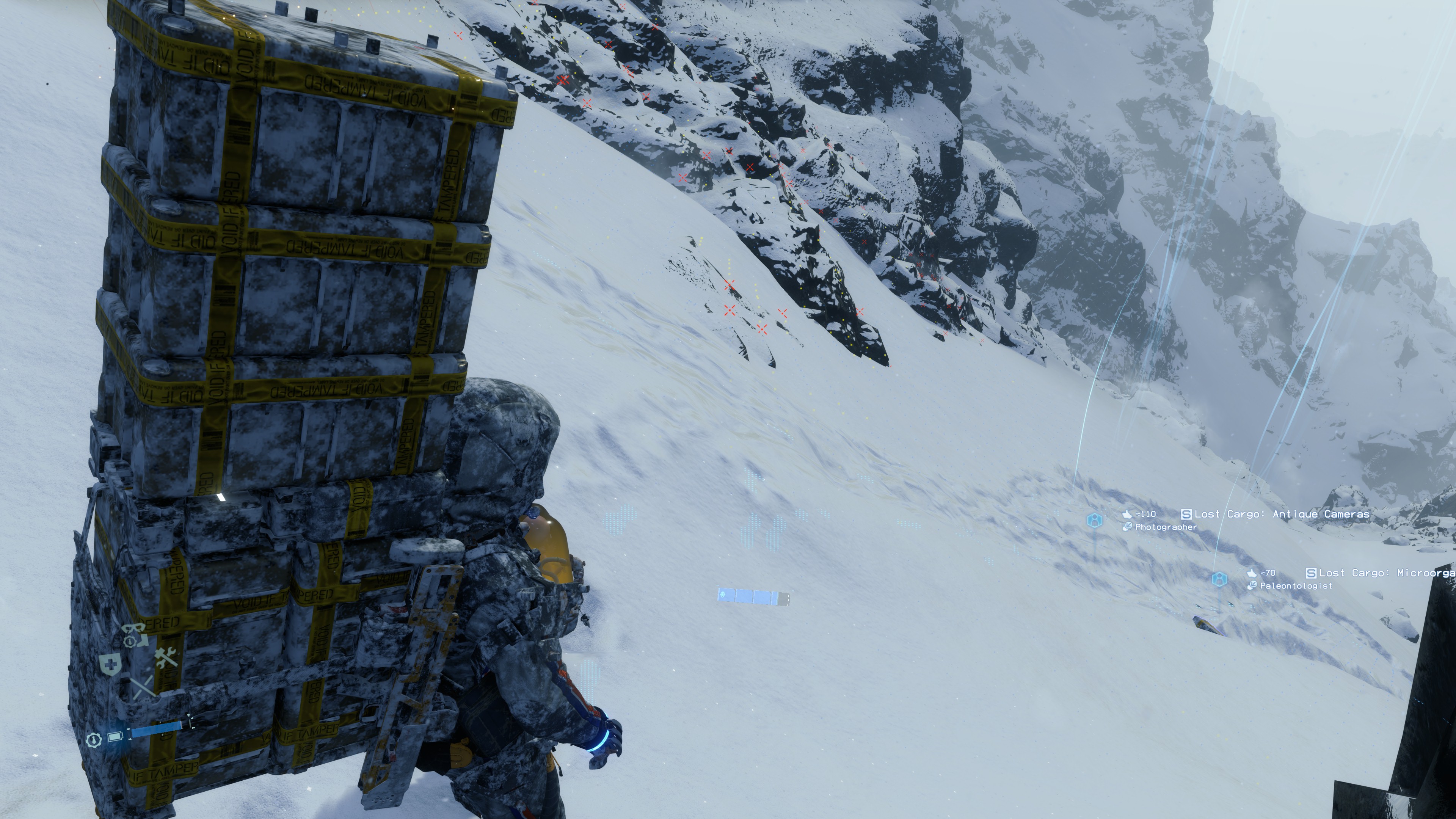
Death Stranding’s Vertex Description – Skinned Gear (Backpack, Metal bars, stuff around Sam)
POSITION         R32G32B32_FLOAT           0
BLENDINDICES     R8_UINT                   12
NORMAL           R32G32B32_FLOAT           0
TANGENT_BFLIP    R32G32B32A32_FLOAT        12
COLOR            R8G8B8A8_UNORM            0
TEXCOORD         R16G16_FLOAT              4
TEXCOORD         R16G16_FLOAT              8
TEXCOORD         R16G16_FLOAT              12
Death Stranding’s Vertex Description – Skinned Hair (another hair variations)
POSITION         R32G32B32_FLOAT           0
BLENDINDICES     R8_UINT                   12
NORMAL           R32G32B32_FLOAT           0
TANGENT_BFLIP    R32G32B32A32_FLOAT        12
COLOR            R8G8B8A8_UNORM            0
TEXCOORD         R16G16_FLOAT              4
TEXCOORD         R16G16_FLOAT              8
Death Stranding’s Vertex Description – Skinned Eyes
POSITION         R32G32B32_FLOAT           0
BLENDINDICES     R16G16B16A16_UINT         12
BLENDINDICES     R16G16B16A16_UINT         20
BLENDWEIGHT      R8G8B8A8_UNORM            28
BLENDWEIGHT      R8G8B8A8_UNORM            32
NORMAL           R32G32B32_FLOAT           0
TANGENT_BFLIP    R32G32B32A32_FLOAT        12
TEXCOORD         R16G16_FLOAT              0
Death Stranding’s Vertex Description – Skinned small objects (Sam’s Dream Catcher for example)
POSITION         R32G32B32_FLOAT           0
BLENDINDICES     R8G8B8A8_UINT             12
BLENDINDICES     R8G8B8A8_UINT             16
BLENDWEIGHT      R8G8B8A8_UNORM            20
BLENDWEIGHT      R8G8B8A8_UNORM            24
NORMAL           R32G32B32_FLOAT           0
TEXCOORD         R32G32B32A32_FLOAT        12
COLOR            R8G8B8A8_UNORM            0
TEXCOORD         R16G16_FLOAT              4
Death Stranding’s Vertex Description – Terrain I
POSITION         R32G32B32_FLOAT           0
NORMAL           R16G16B16A16_FLOAT        12
TANGENT_BFLIP    R16G16B16A16_FLOAT        20
COLOR            R8G8B8A8_UNORM            28
Death Stranding’s Vertex Description – Terrain II
POSITION         R32G32B32_FLOAT           0
COLOR            R8G8B8A8_UNORM            28
Death Stranding’s Vertex Description – Terrain III
POSITION R32G32B32_FLOAT 0
Death Stranding’s Vertex Description – Terrain IV
POSITION R16G16B16A16_FLOAT 0
Death Stranding’s Vertex Description – Grass
POSITION         R16G16B16A16_FLOAT           0
COLOR            R8G8B8A8_UNORM               16
TEXCOORD         R16G16_FLOAT                 20
Death Stranding’s Vertex Description – Flowers
POSITION         R16G16B16A16_SNORM           0
TEXCOORD         R16G16_UNORM                 0
COLOR            R8G8B8A8_UNORM               20
Death Stranding’s Vertex Description – Birds, Fishes, (possibly other school/shoal of mesh particles)
POSITION         R16G16B16A16_SNORM       0
TEXCOORD         R16G16_UNORM             0
TANGENT_BFLIP    R16G16B16A16_SNORM       4
NORMAL           R16G16B16A16_SNORM       12
COLOR            R8G8B8A8_UNORM           20
Death Stranding’s Vertex Description – Boulders, Rocks & Stones I
POSITION         R16G16B16A16_FLOAT       0
TEXCOORD         R16G16_UNORM             0
TANGENT_BFLIP    R16G16B16A16_SNORM       4
NORMAL           R16G16B16A16_SNORM       12
COLOR            R8G8B8A8_UNORM           20
Death Stranding’s Vertex Description – Boulders, Rocks & Stones II
POSITION         R16G16B16A16_FLOAT       0
TANGENT_BFLIP    R16G16B16A16_SNORM       0
NORMAL           R16G16B16A16_SNORM       8
COLOR            R8G8B8A8_UNORM           16
TEXCOORD         R16G16_FLOAT             20
Death Stranding’s Vertex Description – Decals (Footsteps, dirty,…etc.)
POSITION         R16G16B16A16_SNORM       0
TEXCOORD         R16G16_UNORM             0
TANGENT_BFLIP    R16G16B16A16_SNORM       4
NORMAL           R16G16B16A16_SNORM       12
Death Stranding’s Vertex Description – Water (Lake)
POSITION         R32G32B32_FLOAT          0
TANGENT_BFLIP    R16G16B16A16_SNORM       0
NORMAL           R16G16B16A16_SNORM       8
COLOR            R8G8B8A8_UNORM           16
Death Stranding’s Vertex Description – Water II (Lake, Waterfall,..etc.)
POSITION         R32G32B32_FLOAT          0
TANGENT_BFLIP    R16G16B16A16_SNORM       0
NORMAL           R16G16B16A16_SNORM       8
COLOR            R8G8B8A8_UNORM           16
TEXCOORD         R16G16_FLOAT             20
Death Stranding’s Vertex Description – Water III (Ocean)
POSITION         R32G32B32_FLOAT          0
COLOR            R8G8B8A8_UNORM           0
TEXCOORD         R16G16_FLOAT             4
And much more….
Copy & Clear
Streaming Tiles Clustering [Compute]
A handful amount of dispatches in form of few compute passes queued one after another that works on world clustering to prepare for culling by defining visibility & visible instances across the view. A whole lot of data passed to such dispatches in order to work, such as:
Query Global Bindings Constant
struct mQueryConstants
{
	uint mFlags;
	int3 mFloatingOrigin;
	uint mBatchCapacity;
	uint mInstanceCapacity;
	uint mPlaneCount;
	uint mSubFrustumCount;
	uint mPackedPerFrustumShadowCastingBits;
	uint mOcclusionMipCount;
	uint mOcclusionWidth;
	uint mOcclusionHeight;
	uint4 mOcclusionViewport;
	float4 mThresholdAndLodScaleSquared;
	float4 mViewPosAndHalfDiag;
	float4[8] mFrustumPlanes;
	float4x4 mPrevViewProj;
	float4[24] mSubFrustumPlanes;
	float4[2] mSubFrustumThresholds;
	float4 mSubFrustumLodDistancesSquared;
	float4 mLodOverrideRangeSquared;
}
Query Cluster Bindings
struct mQueryClusterBindings
{
	uint mInstanceCount;
	uint mTileInstanceOffset;
	uint mGlobalInstanceOffset;
	uint mTileIndex;
	uint mDisableFlags;
	uint mClusterFlags;
}
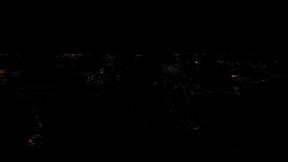
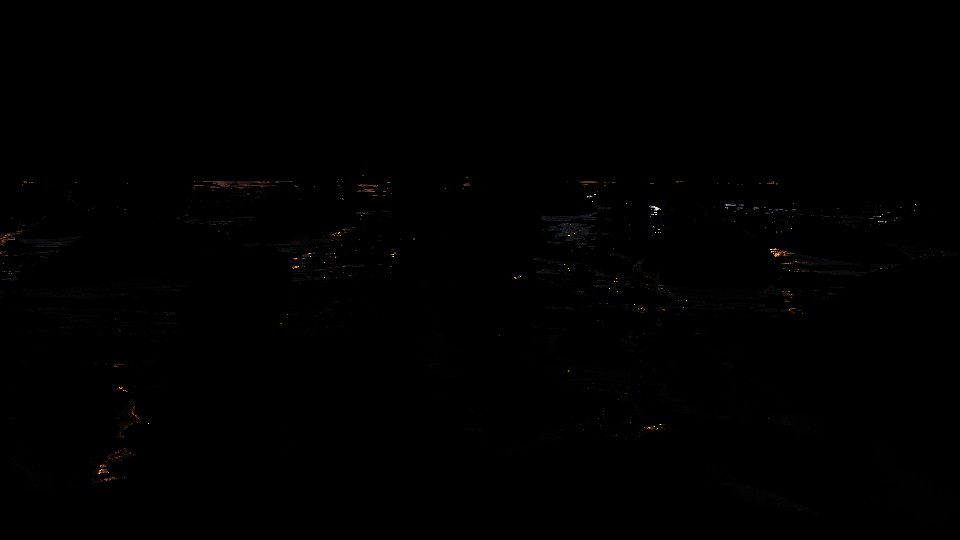
And for some reason it takes the downsampled occlusion texture of the previous frame as an input. This texture mostly holding values during cinematics, and usually black 1*1 during gameplay (culling takes place under multiple techniques anyways).


Streaming Priority [Compute]
Not very clear the exact details about what is going on here, but with a given GroupData, this few compute dispatches working on outputting a buffer of int values that represents the streaming’s PriorityOutputData using the following set of params.
Streaming Priority GPU Compute Job Resources Constant
struct mStreamingPriorityGPUComputeJobResources_Constant
{
	int mViewCount;
	float mMeshSafetyFactor;
	float mBoundingBoxPriority;
	int mPadding;
	float4x4 mViewPositionAndDeprioritizeMultiplier;
	float4x4 mViewDirectionAndLODDistanceScale;
	float4x4 mViewEncodedFOVData;
	float4x4 mDOFNearSettings;
	float4x4 mDOFFarSettings;
	float4 mPriorityComputationSettings;
	int4 mHintDataTypes;
}
Streaming Check Activation [Compute]
With a given buffer full of ObjectBoundingBoxData and a buffer of ObjectActivationStateAndResuseIndex in order to fill a RW buffer with some data for the streaming system.
Streaming Check Activation Compute Job Resources Constant
struct mStreamingCheckActivationComputeJobResources_Constant
{
	int mViewCount;
	int3 mPadding;
	float4x4 mViewPositionAndDistanceScaleSquared;
}
The mViewCount value is kinda interesting because it always vary which is not usually the case, at least in gameplay, you’ve got 1 view to decide what active/visible and what not. Not super sure the factor behind that, or which values are meant here, but here are some variations of that value, and yes, it is not something based on being cinematic or gameplay, nope!


World Data Probe Texture Copy [Compute]
A compute pass with few dispatch that which does copy some texture tiles from the world, into buffers. Those buffers needed shortly as input for another compute jobs that is targeting verity of goals. Such as simulation force fields, rain, water, clouds, snow interaction,….etc.
World Data Probe Texture Copy CB
struct WorldDataProbeTextureCopyCB
{
	int4 mTextureChannels;
	int mSourceRectTop;
	int mSourceRectLeft;
	int mTileTextureSize;
}
World tile textures that get copies are like those ones for example


Particles Update [Compute]
Few dispatches where writing simulation data to some buffers
Particle Update Compute Params
struct mParticleUpdateComputeParams
{
	float4x4 mViewMatrix;
	float4x4 mInvViewMatrix;
	float4x4 mPrevViewMatrix;
	float4x4 mViewProjMatrix;
	float4x4 mDepthReconstructionMatrix;
	float mTimeStep;
	int mSystemFlags;
}
GPU Particle
struct GPUParticle
{
	float4 mPositionAndSize;
	float4 mVelocityAndRandom;
	float4 mRotation;
	float4 mPreviousRotation;
	float mPreviousSize;
	uint mPackedFlagsAndAge;
	uint mLifeSpanAndForceFieldIndex;
	uint mColor;
}
GPU Particle System Stats
struct GPUParticleSystemStats
{
	int mBoundsMinX;
	int mBoundsMinY;
	int mBoundsMinZ;
	int mBoundsMaxX;
	int mBoundsMaxY;
	int mBoundsMaxZ;
	int mAliveParticleCount;
	int mDeadParticleCount;
	int mParticleValidationInfo;
}
Force Field Sample
struct ForceFieldSample
{
	float4 mPositionAndMass;
	float4 mSurfaceAreaVector;
	float4 mVelocityAndWaterFlowScale;
	int mCategoryMask;
}
Force Field [Compute]
Few dispatches to compute the force fields and write the data out into the force field sample results structures.
Force Field Sample Result
struct ForceFieldSampleResult
{
	float4 mFlow;
	float4 mWaterFlow;
	float3 mForce;
}
Force Field Compute Params
struct ForceFieldComputeParams
{
	float4 mWorldToWaterHeightScaleBias;
	float4 mWorldToWaterFlowScaleBias;
	float mWaterHeightRangeMin;
	float mWaterHeightRangeMax;
	int mEnableWaterForces;
	int mForceFieldCount;
	int mSampleCount;
	float mTime;
	float mTimeStep;
}
Force Field to Texture [Compute]
This is a later dispatched to write those buffer data generated in the previous step into some 3d textures.


Force Field to Texture Compute Job Params
struct ForceFieldtoTextureComputeJobParams
{
	uint mForceFieldCount;
	float mTime;
	float mTimeStep;
	float mBlendAttack;
	float4 mGridOrigin;
	float4 mGridStepSize;
	int4 mGridDisplacement;
	int4 mTextureSize;
	float mSpecialStiffness;
	float mSpecialDrag;
	float mSpecialMass;
	float mSpecialScale;
	float mSpecialClamp;
	int mSpecialMaxPriority;
	uint mSpecialMode;
	uint mSpecialCategoryMask;
	float mGrassStiffness;
	float mGrassDrag;
	float mGrassMass;
	float mGrassScale;
	float mGrassClamp;
	int mGrassMaxPriority;
	uint mGrassMode;
	uint mGrassCategoryMask;
	float mPlantStiffness;
	float mPlantDrag;
	float mPlantMass;
	float mPlantScale;
	float mPlantClamp;
	int mPlantMaxPriority;
	uint mPlantMode;
	uint mPlantCategoryMask;
	float mTreeStiffness;
	float mTreeDrag;
	float mTreeMass;
	float mTreeScale;
	float mTreeClamp;
	int mTreeMaxPriority;
	uint mTreeMode;
	uint mTreeCategoryMask;
}
Image Blend [Compute]
Generate the 3d lookup table (32*32*32 – RGBA8_UNORM) that will be used by the end of the frame as a fragment shader resource in the post-processing applying step.

Image Blend Compute Constants
struct ImageBlendComputeLayerInfo
{
	int mOperation;
	float mAmount;
	float mPadding0;
	float mPadding1;
}

struct ImageBlendComputeConstants
{
	ImageBlendComputeLayerInfo[16] mLayers;
	int mLayerCount;
	int mPreExpose;
	float mExposureScale;
}
Linear Buffer [Compute]
//TODO
Plant Compute [Compute]
//TODO
Copy & Clear
Yet another ClearRenderTargetView()
Clear Depth Stencil View
Just before jumping to the next steps where snow/mud interaction is handled, a ClearDepthStencilView() runs after we’ve already copied the previous frame data in the previous step..
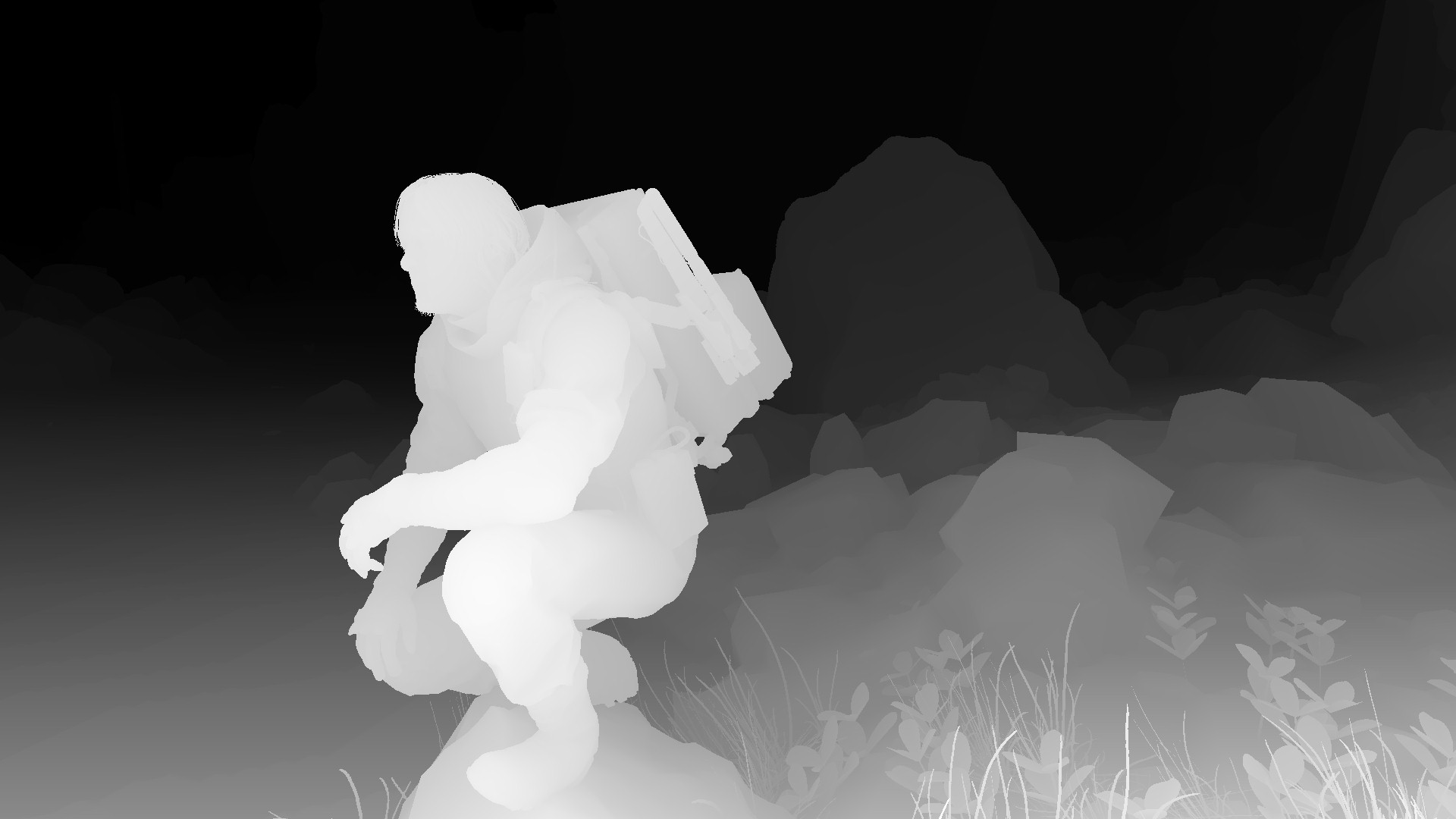
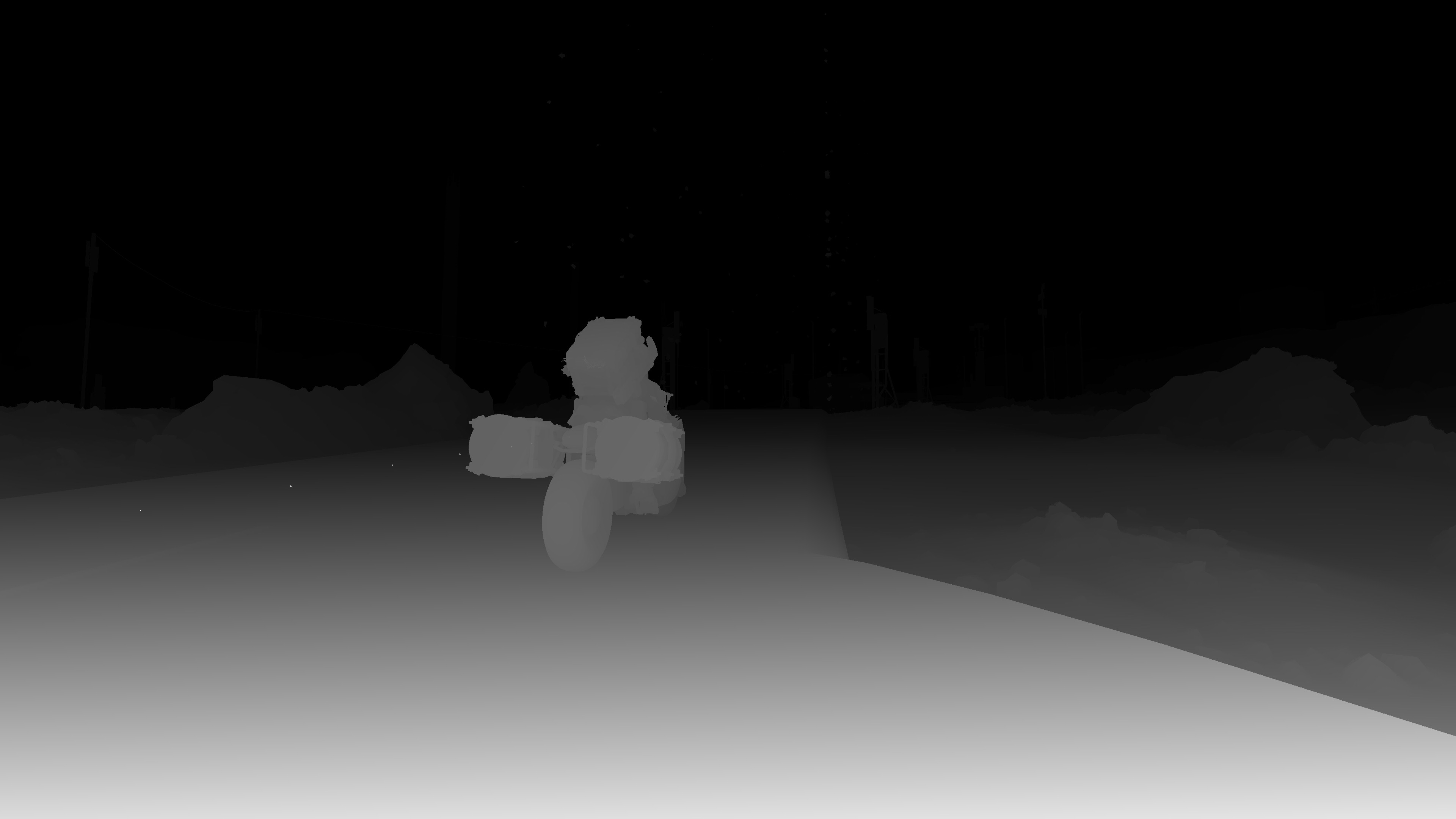
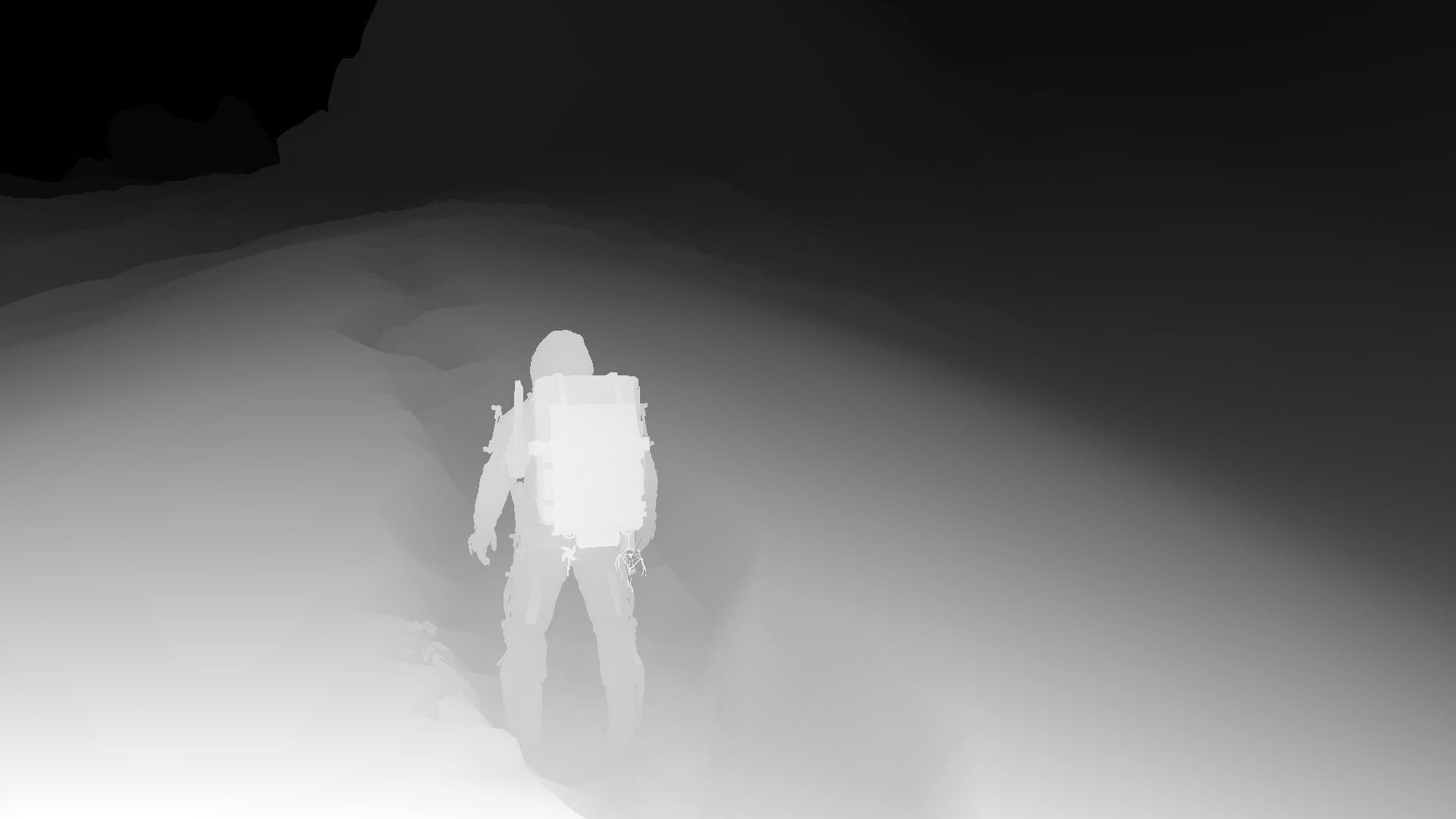
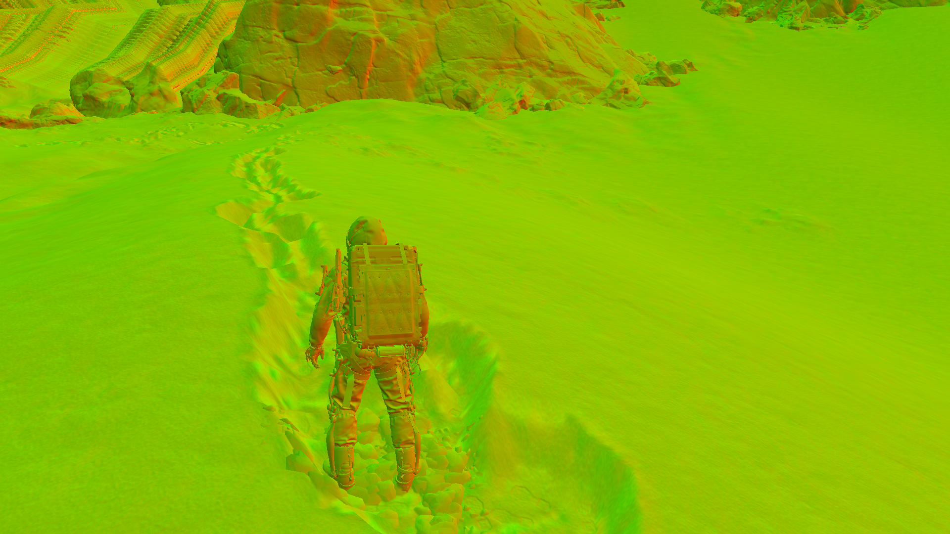
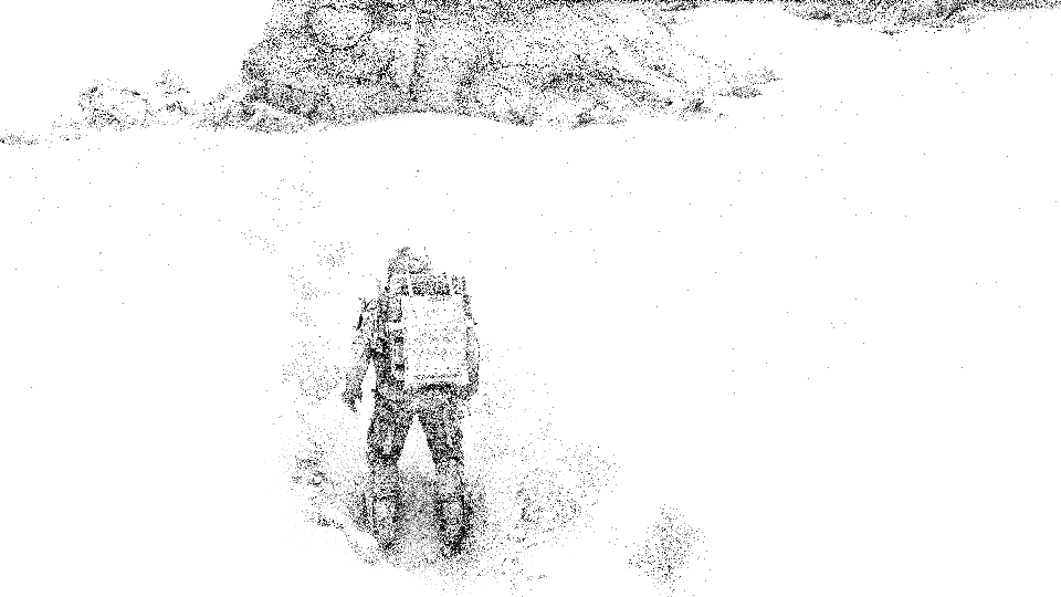
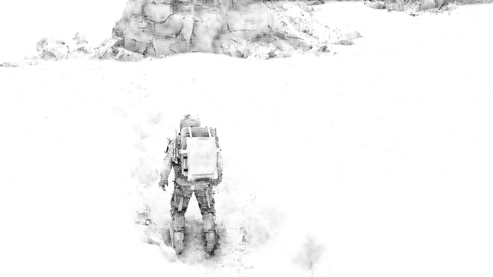
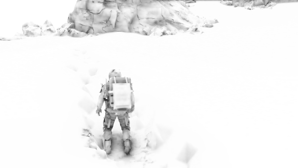
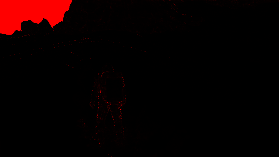
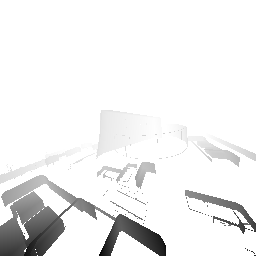
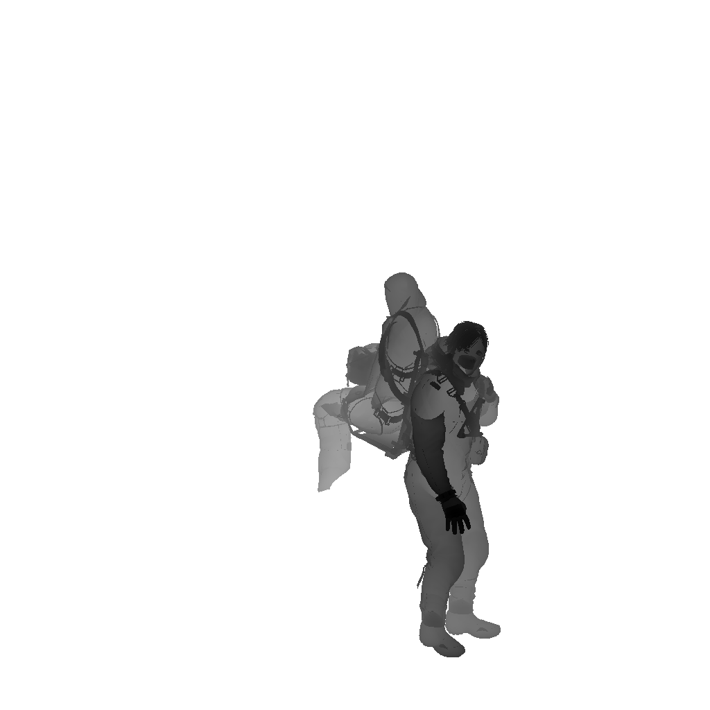
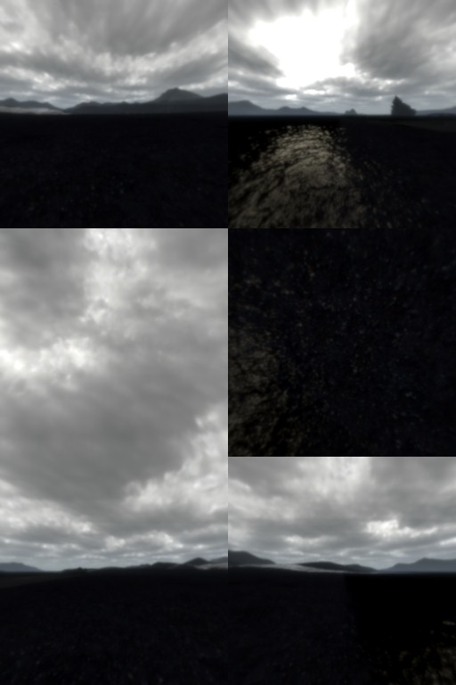
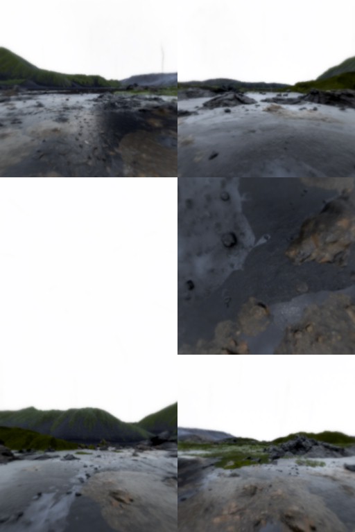
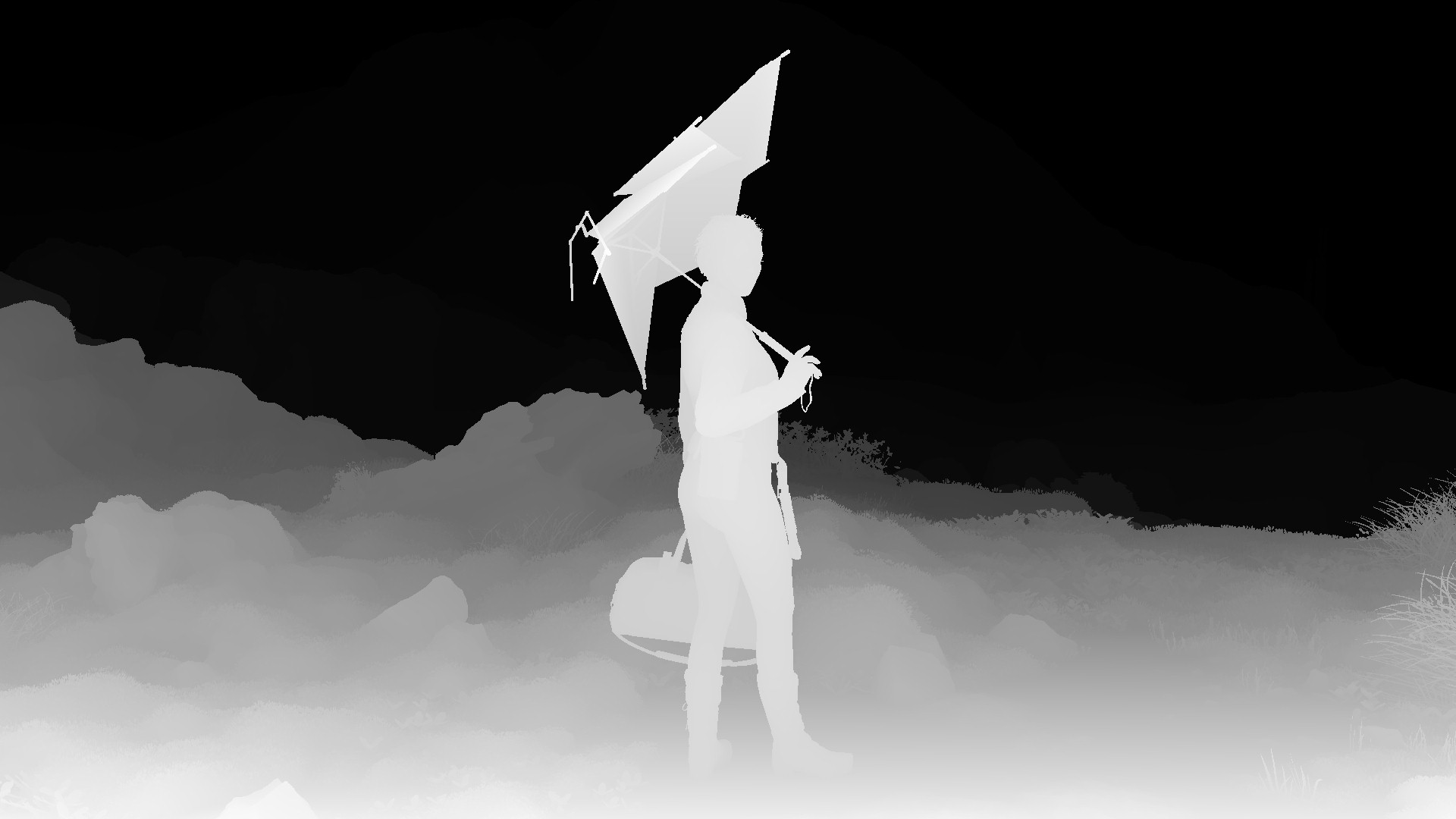
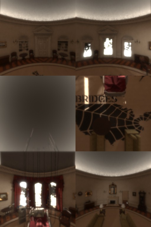
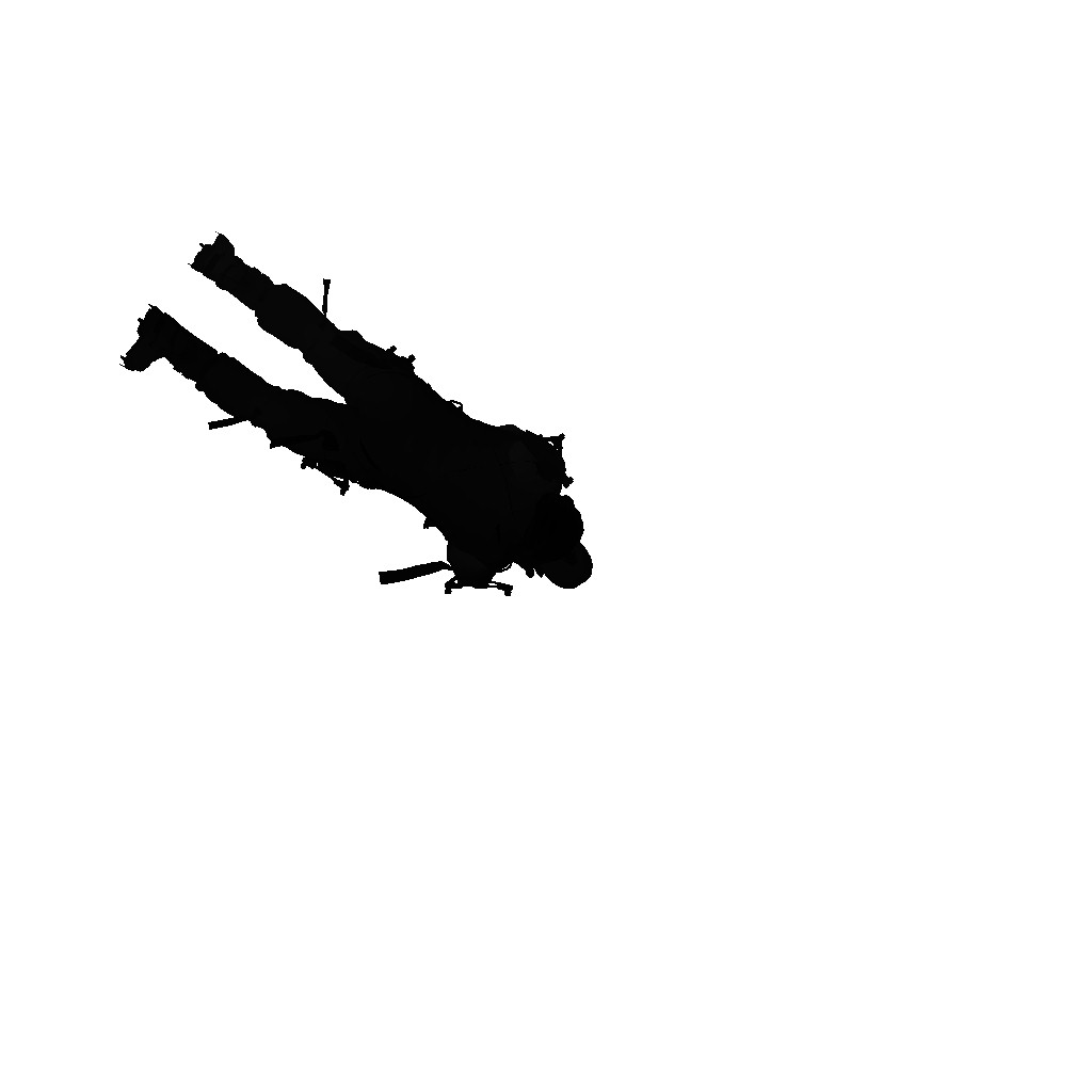
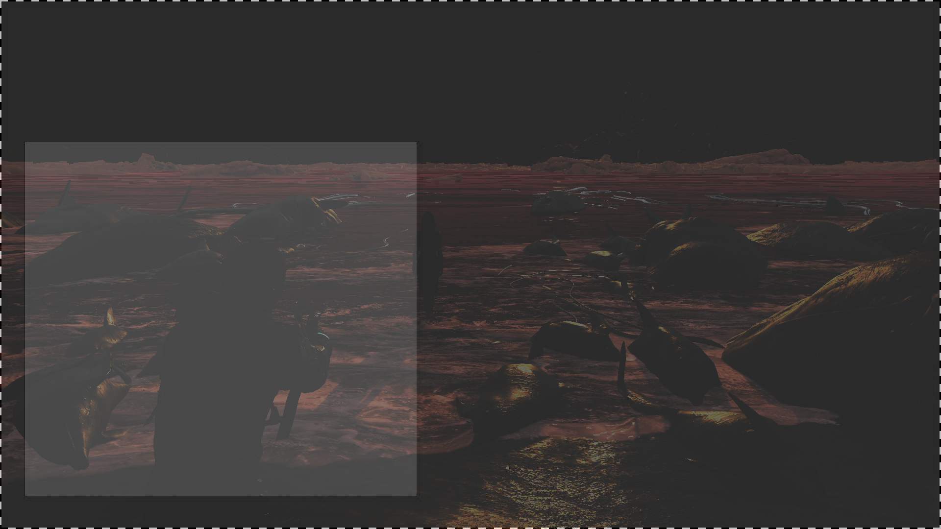
Snow/Mud Top View Depth Pass
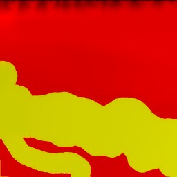
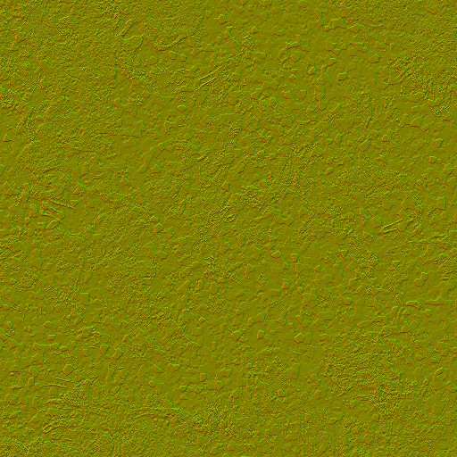
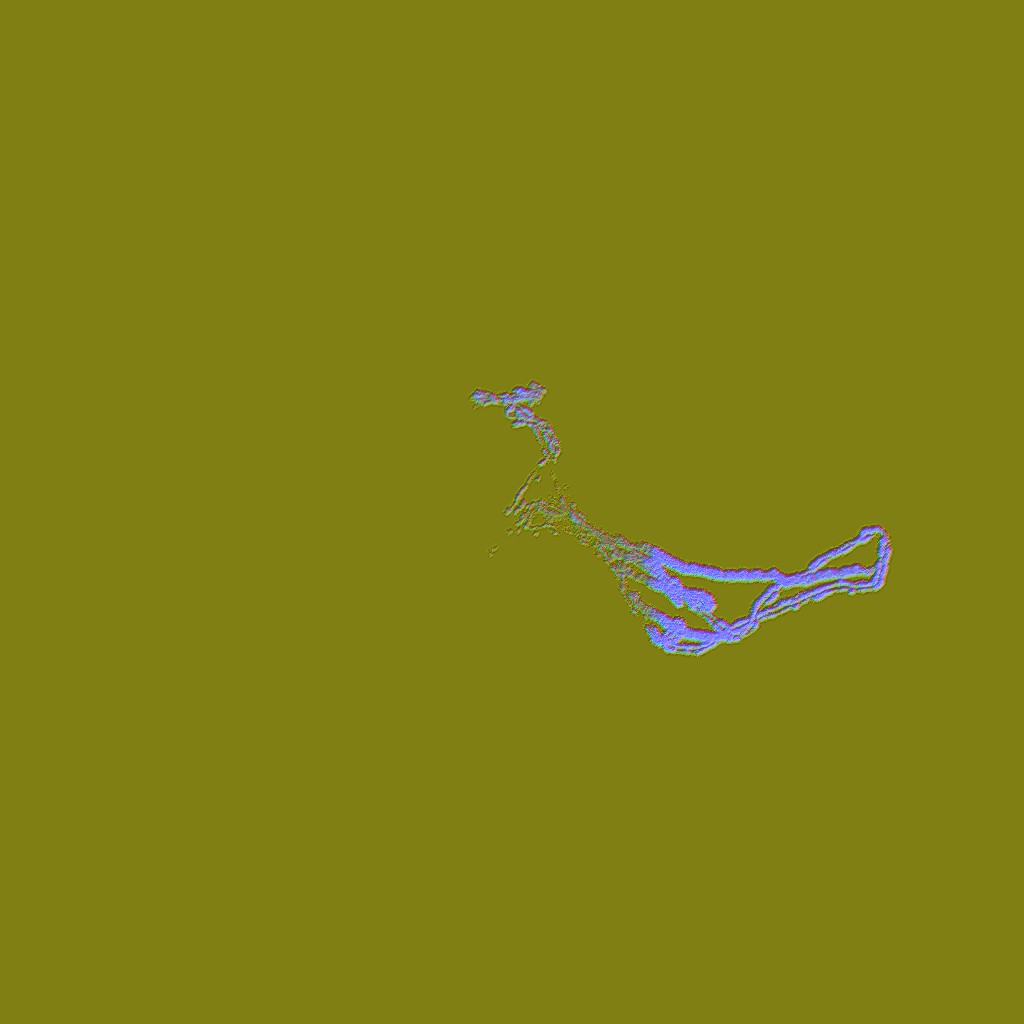
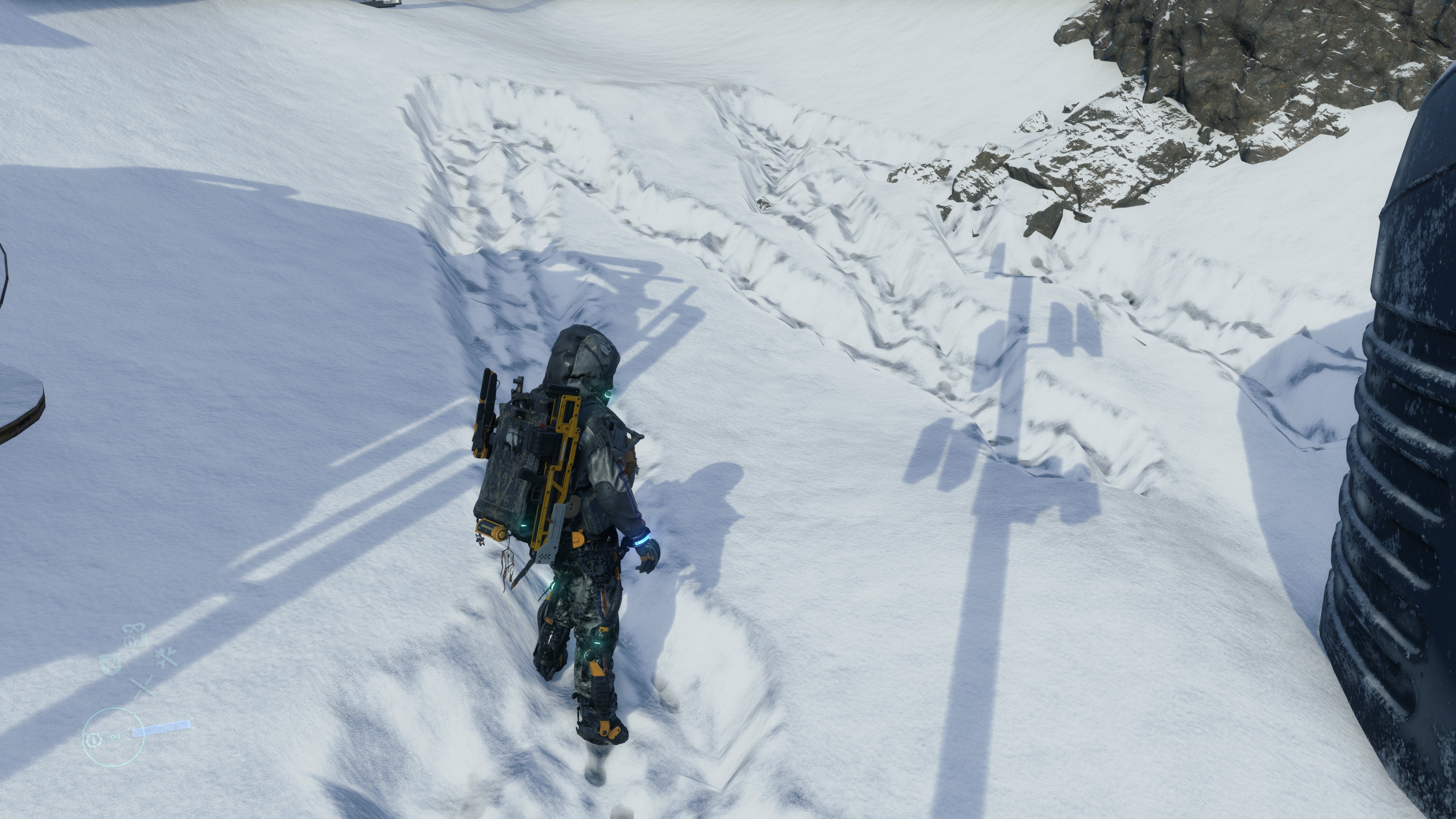
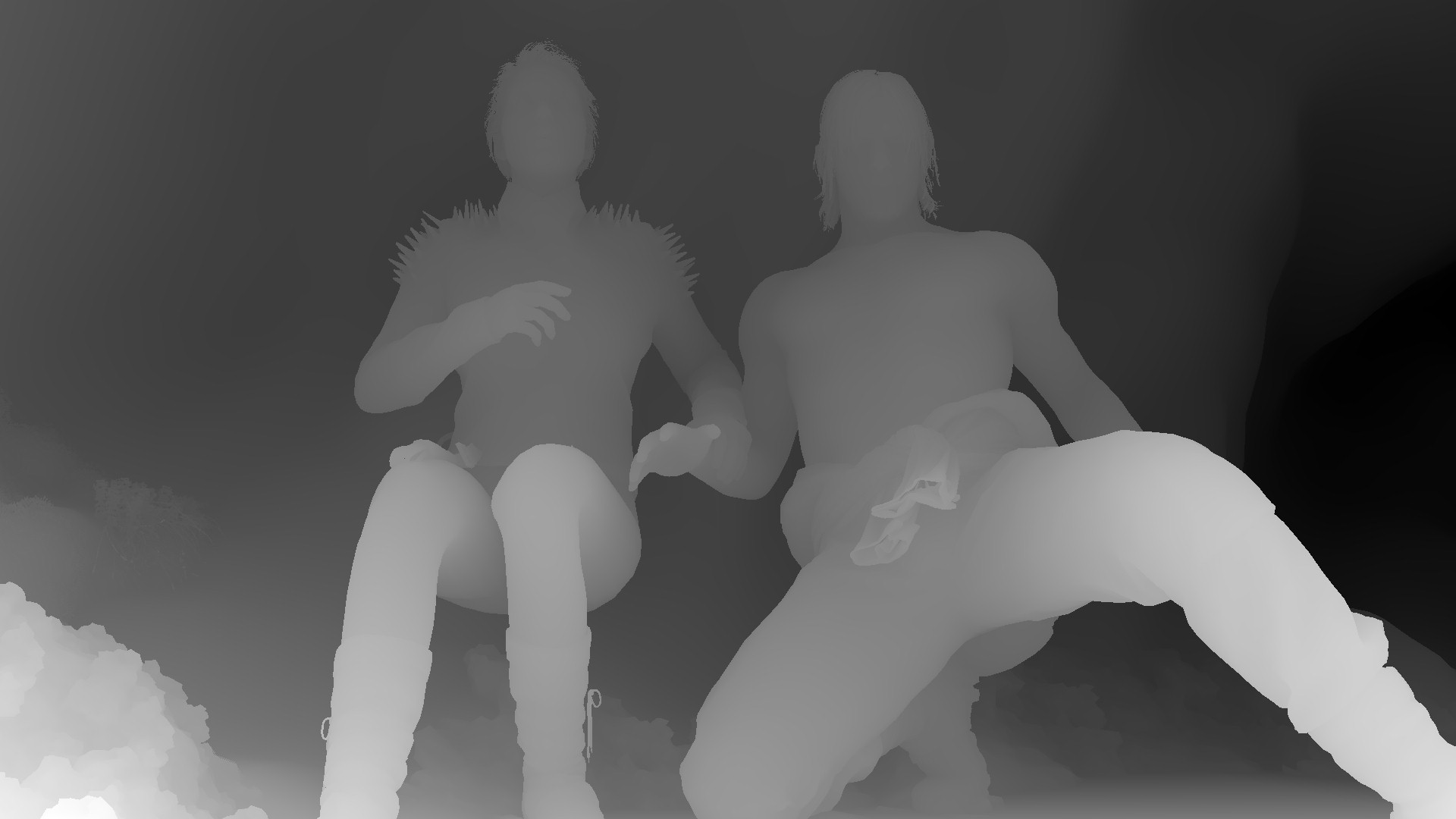
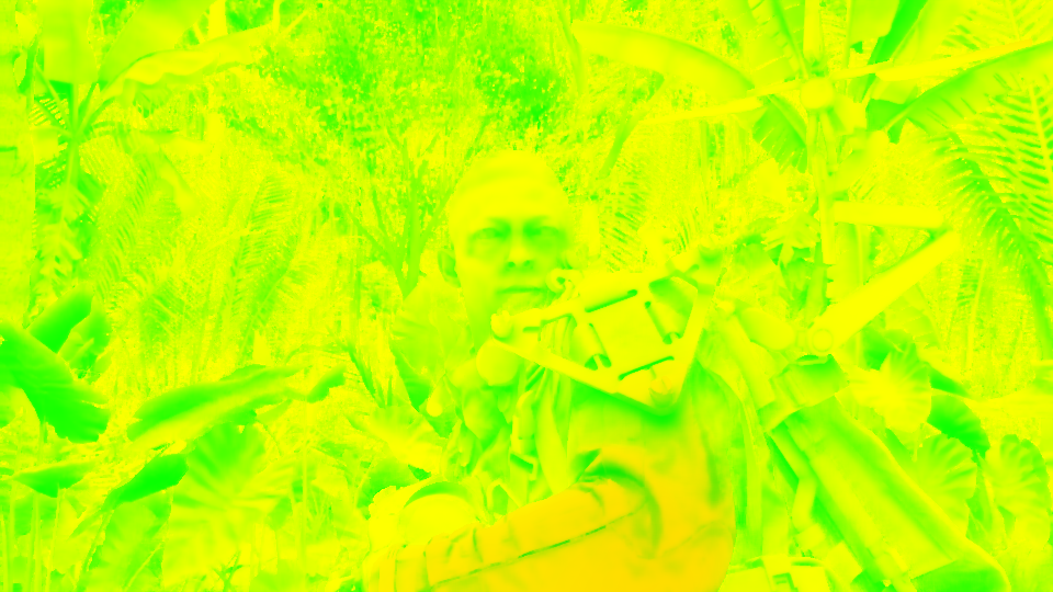
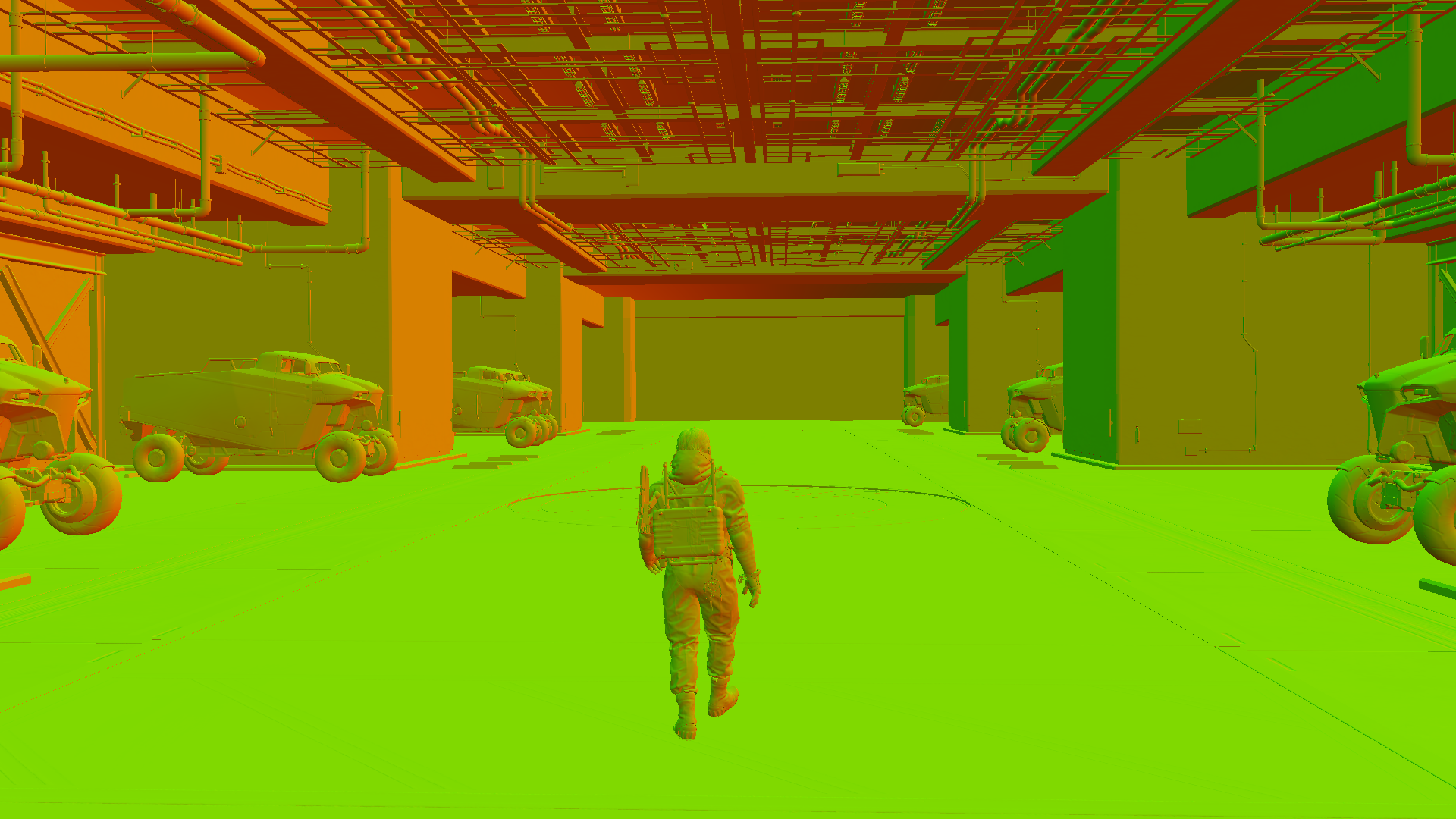
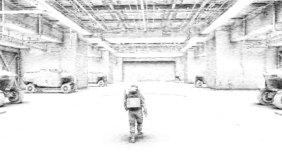
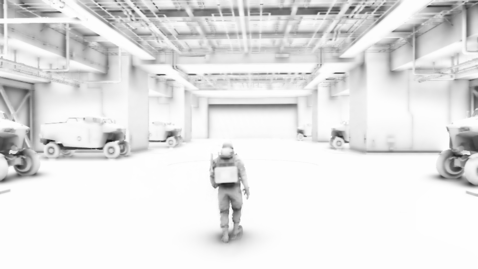
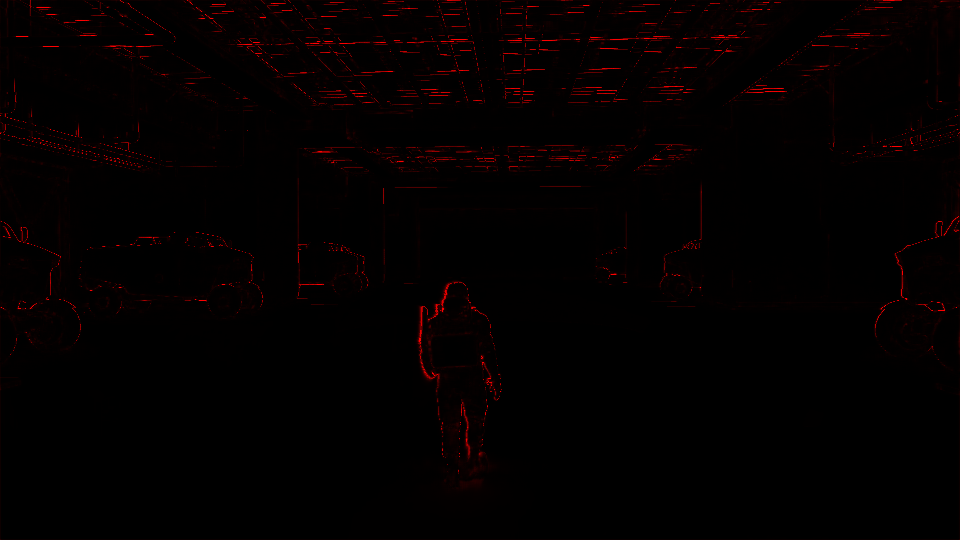
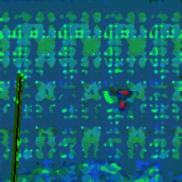
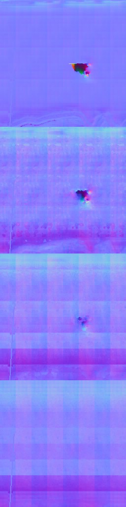
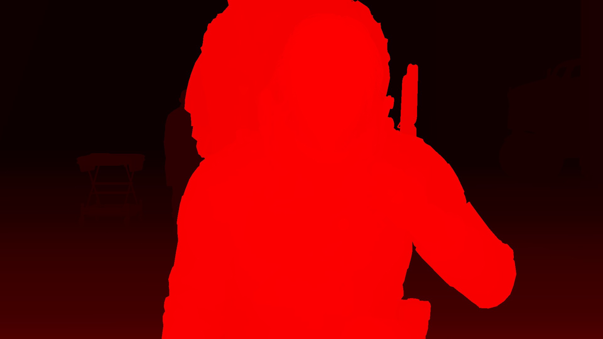
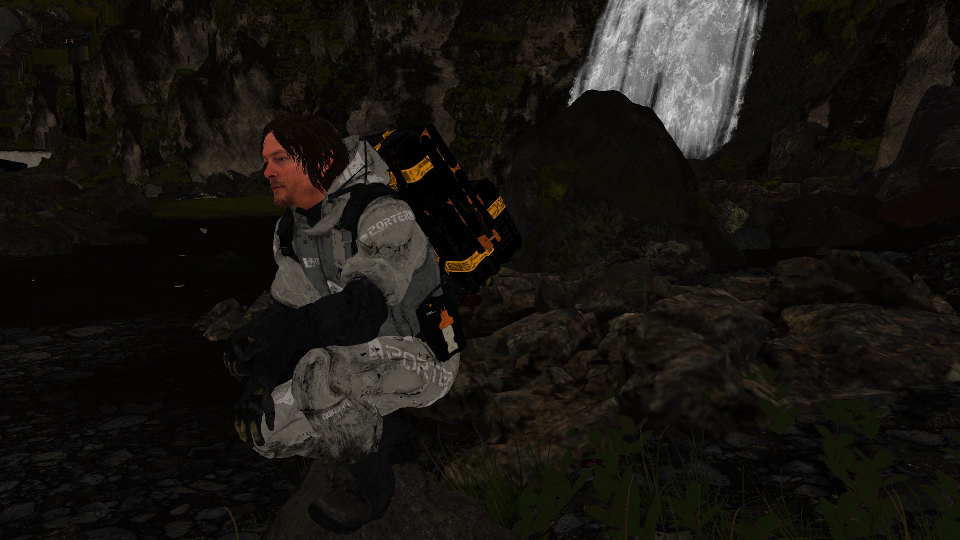
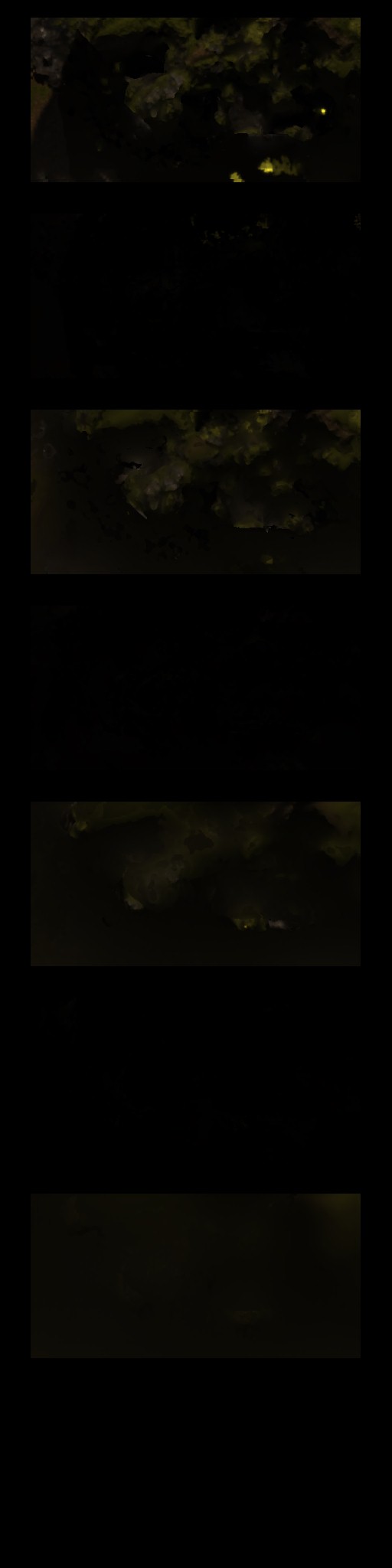
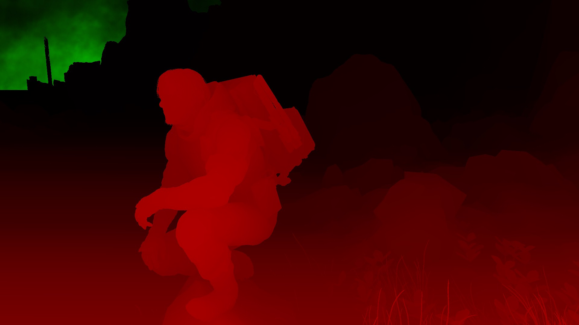
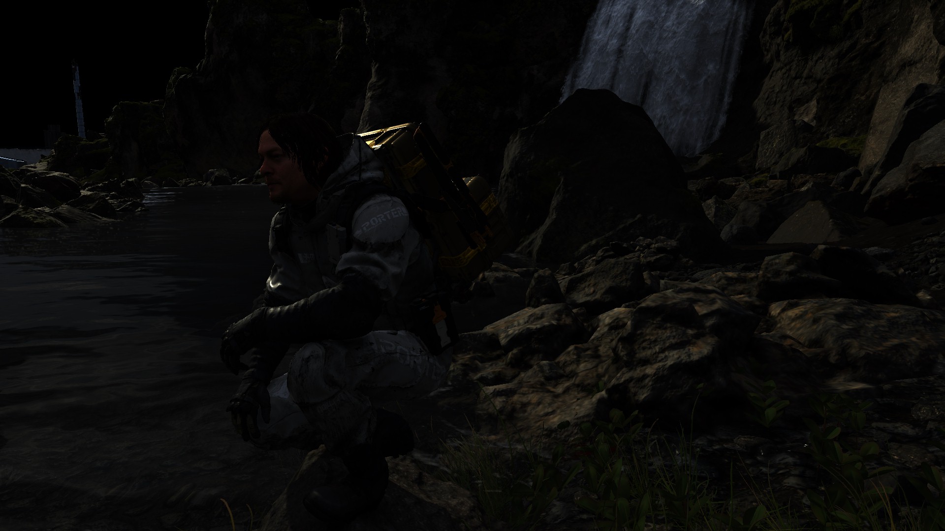
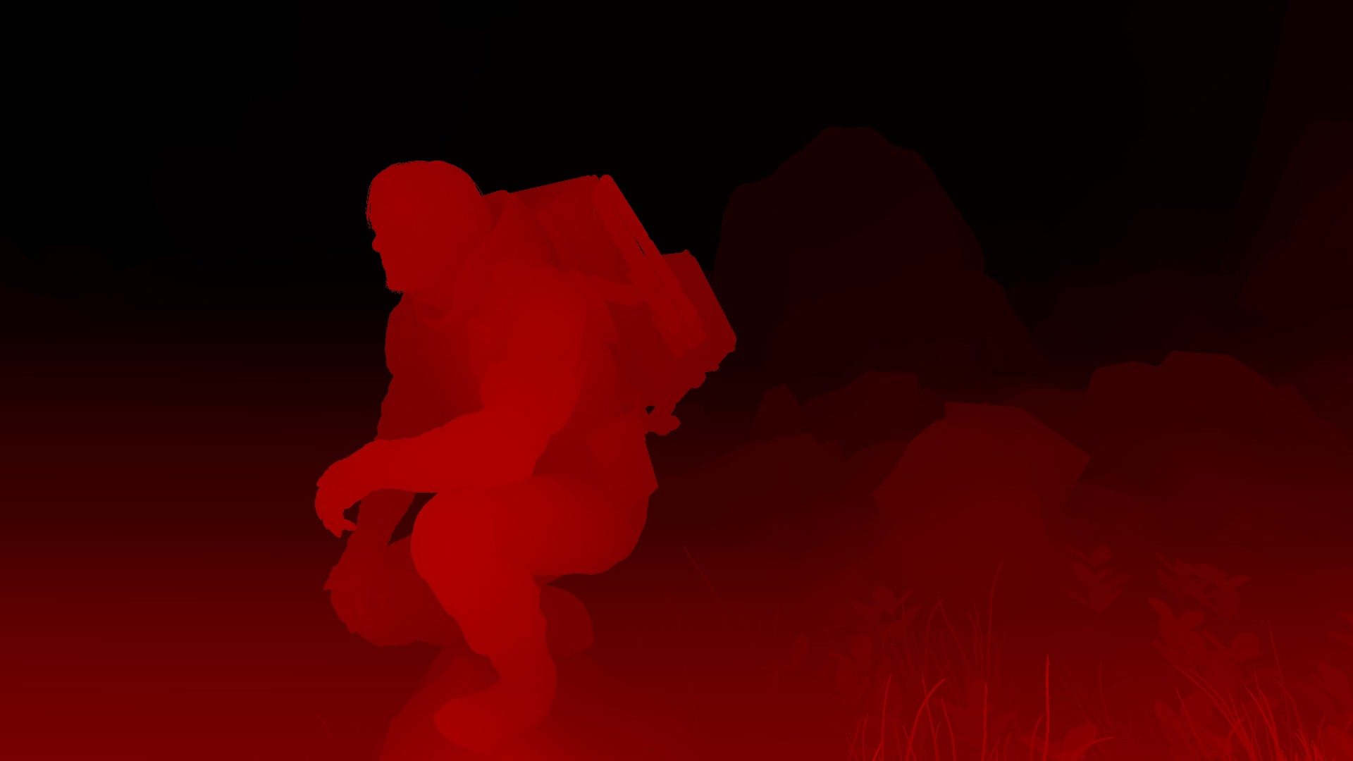
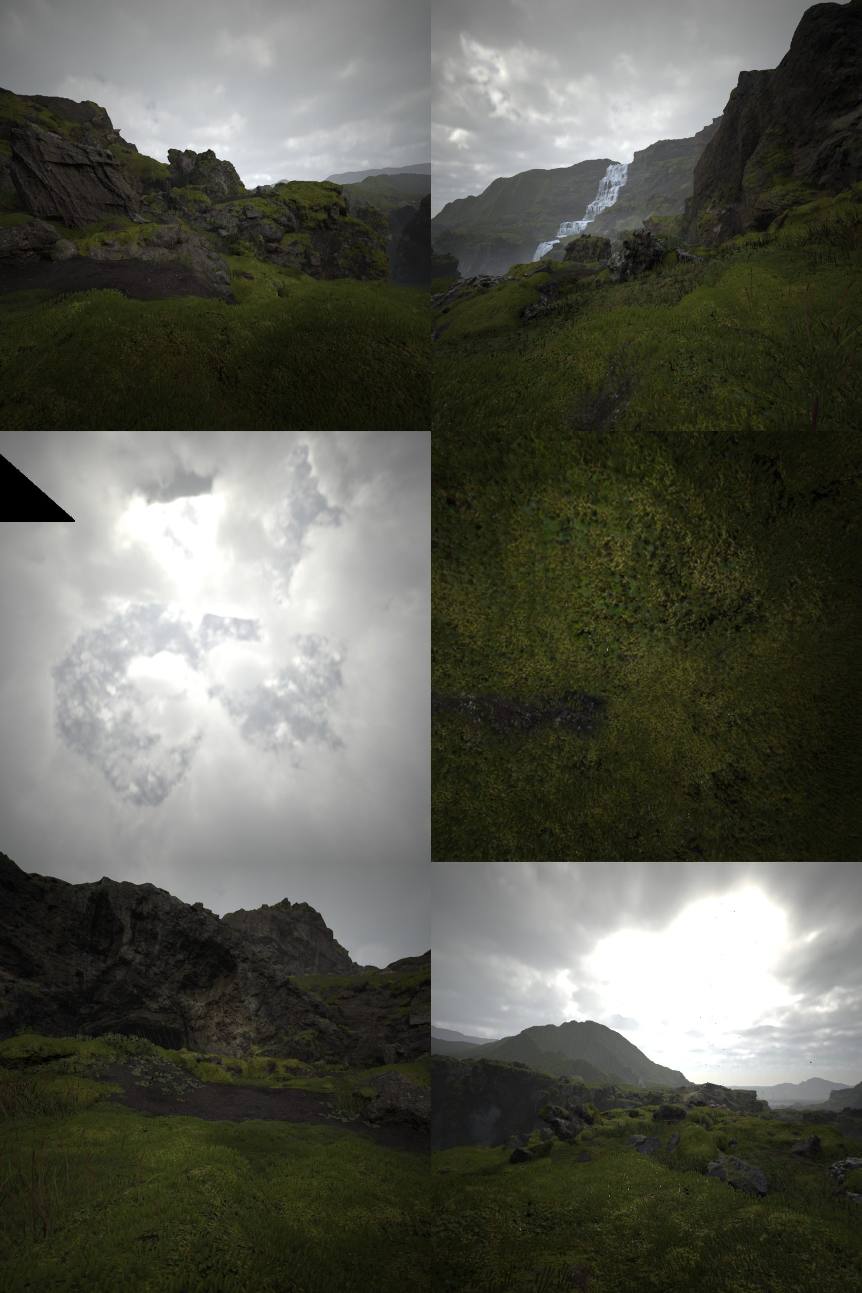
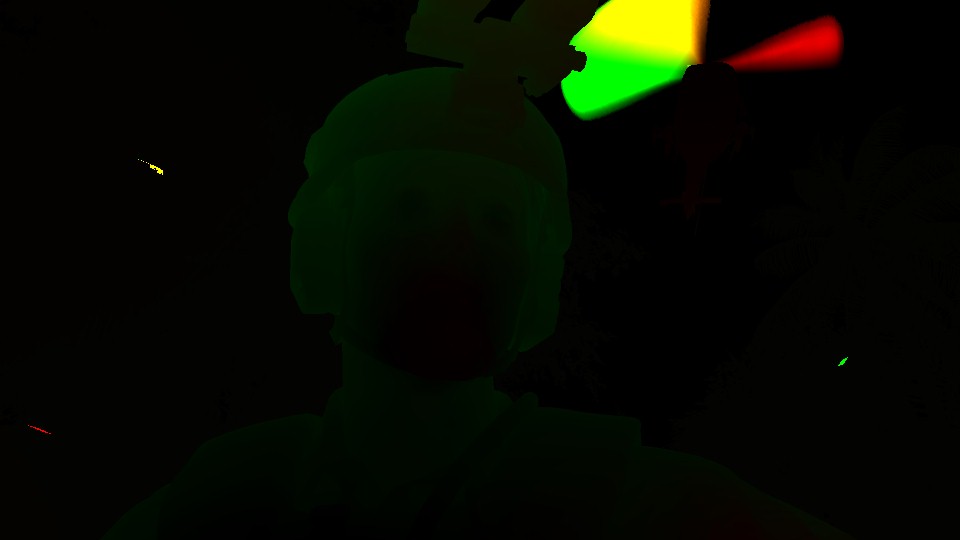
Few sequential DrawIndexedInstanced() in order to Outputs a 1024*1024 – R16_TYPELESS, this is needed in the next step to compute the snow/mud interaction. In this pass, It seems it draw only a low resolution version of the meshes, and it makes sese considering the camera is far away at the top, and hence a low LOD is utilized. Most of the time this is about Sam, but other times would be Characters or vehicles.


This is always taking place, regardless there is snow or not. Even in Jungle level, still taking place.
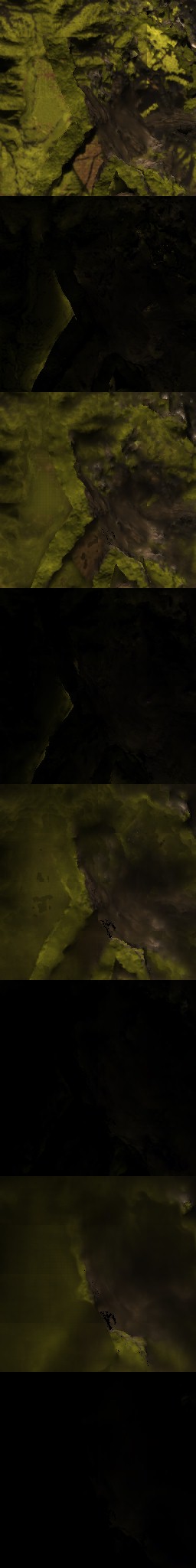
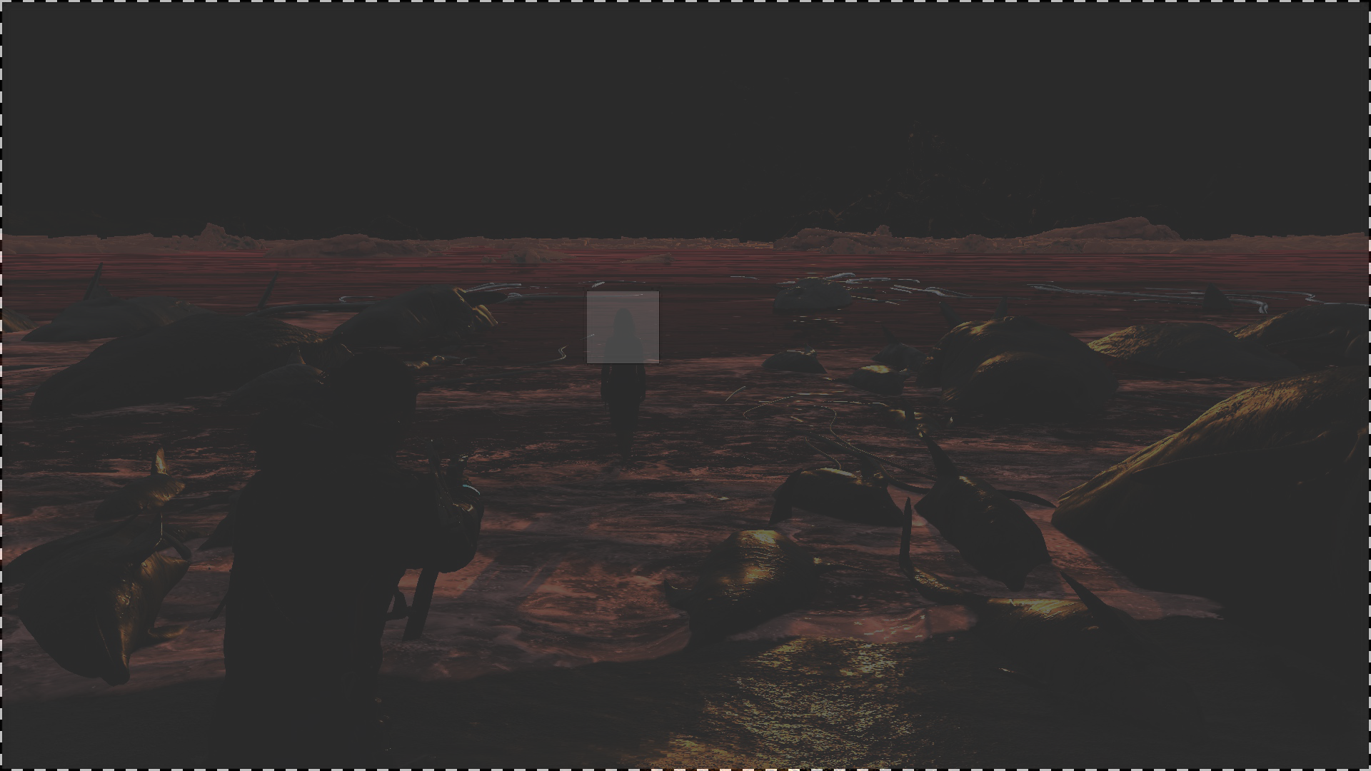
Snow Interaction Update [Compute]
This pass only takes place when there is snow/mud. So with the fact that top view depth always get kicked, but here it only happened when there is actual surfaces to deform.
The exact details of the compute is something to investigate further, but yet, it is only working with those given inputs to produce the new deformation textures/buffer that will be used to deform the tessellated terrain later while drawing the GBuffer.


Snow Interaction Update Params Constant
struct SnowInteractionUpdateParamsConstant
{
	float4 mProbeTextureScaleBias;
	float4 mProbeTextureHeightRange;
	float2 mWSInteractionCenter;
	float2 mSampleOffset;
	float mSampleDistanceTimes2;
	float mInteractionAreaWorldSize;
	float mInteractionTextureResInv;
	float mInteractionTextureResMinus1;
	float mInteractionTextureResMinus1Inv;
	float mTemporalFilterFactor;
	float mMaxSnowDepth;
	float mMaxSnowDepthInv;
	float mLinNormDepthToWorldScale;
	float mLinNormDepthToWorldBias;
	float mDeltaTime;
	float mNonUniformExponent;
	float mInitialDeformation;
	float mTerrainOffset;
	float mNormalTiling;
	float mNormalIntensity;
}
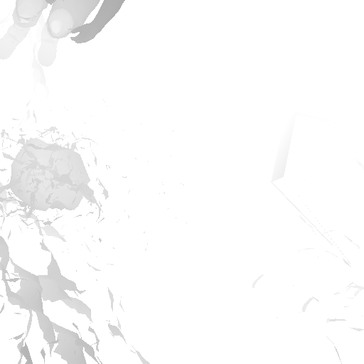
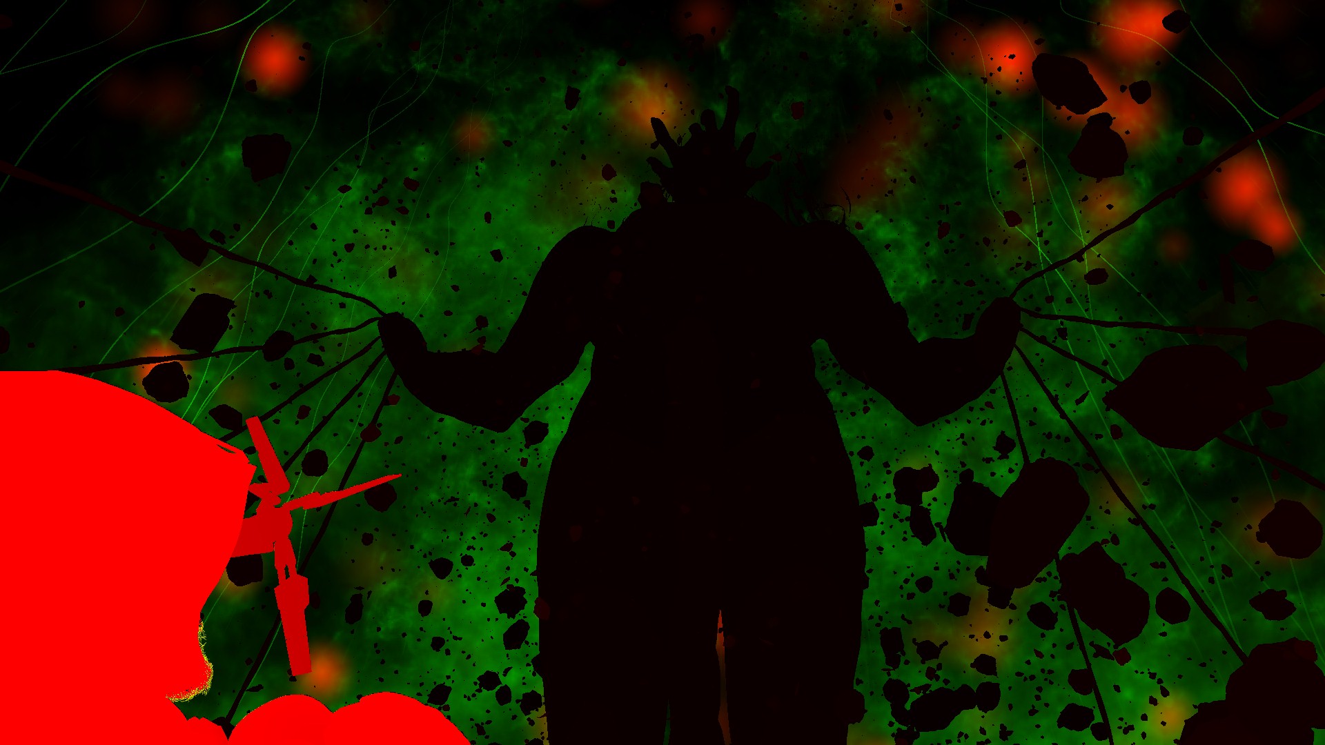
And to make it more clear, and becaue i’ve the luxury of owning a very short nickname that is just one letter & easy to type on snow with a walking delivery CG character, here it is… M


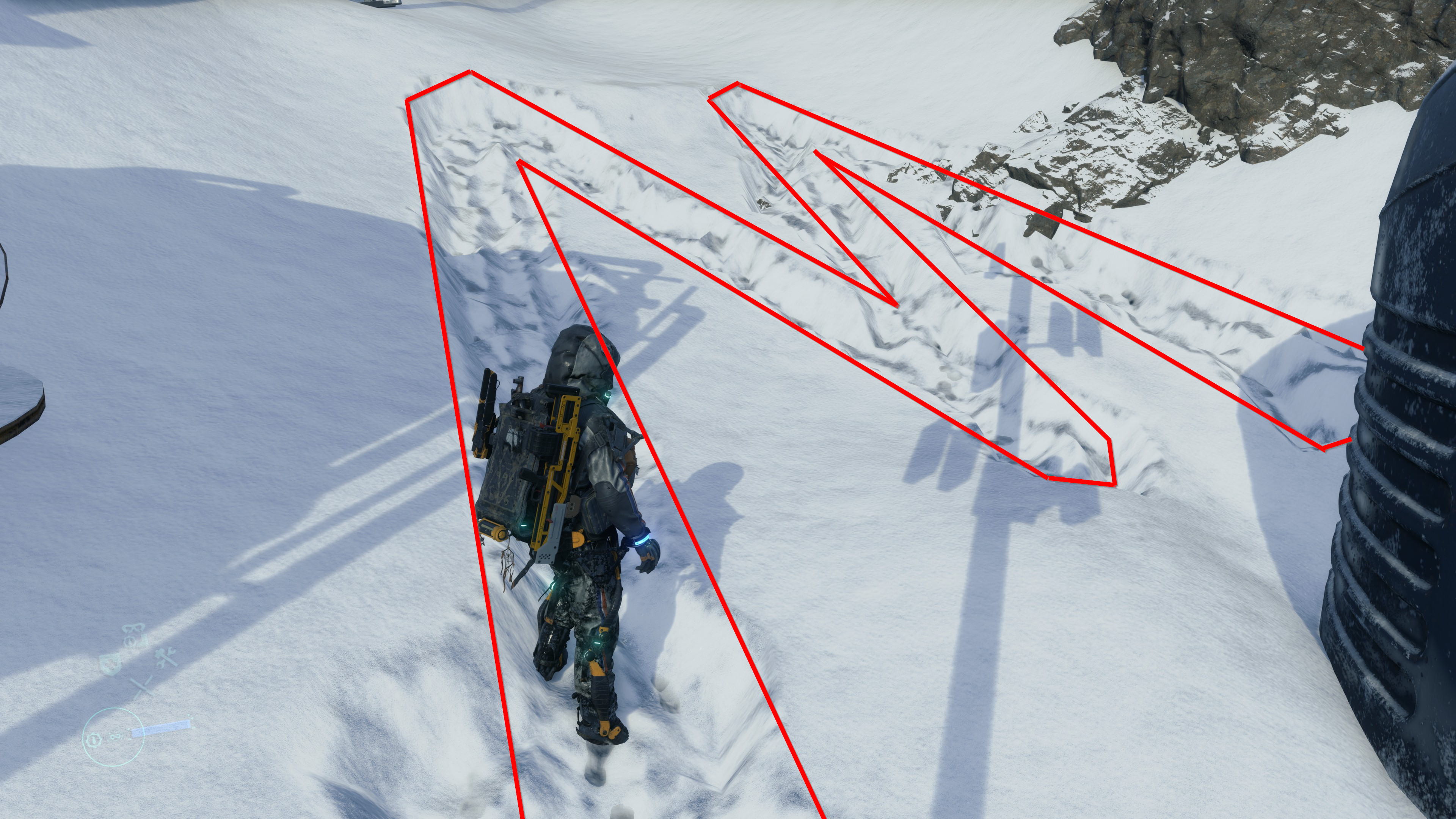
Keep in mind that the rendertarget is always “mirrored” because the top-view camera orientation is different than your third person camera orientation. You can easily observe that below, specially due to the rocky area where no deformable snow covering it.

Anyways, by the end of this pass, the output Deformation texture get copied to a buffer, this to be utilized by the next frame. So basically anything that will accumulate, is copied as buffers, kept aside, and then re-used in the next frame (mostly in the next frame it is changing it’s form from buffer to a rendertarget back again). And of course, the Deformation texture itself, is used shortly during the GBuffer to deform the tessellated terrain mesh.
Copy & Clear
Yet another ClearRenderTargetView()
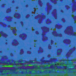
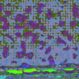
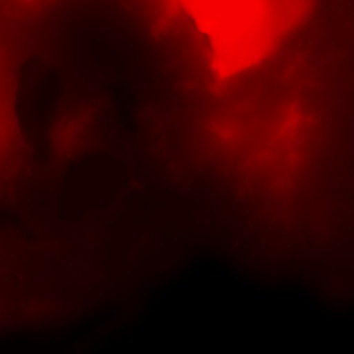
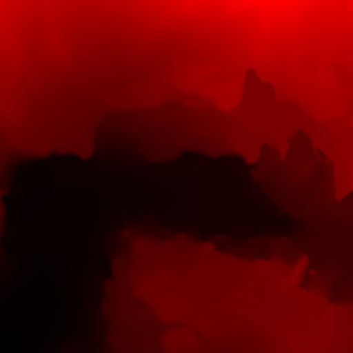
Cloud Density
With some cloud textures, and a RainyMap (this is a compute output that is discussed below), we get the what so called the Cloud Density texture. You can think about this step as, wherever there is rain, then there is clouds, then let’s consider this area cloudy. The more rain, the dense the clouds at this location. Rain coming from the sky, not from the empty spaces!


So, basically in all game frames, the RGB will be the same, as it uses the same input cloud samplers always, but the A channel is what differs between frames
Precipition Occlusion Height
Nothing very detailed here, but at this step there is a rendertarget generated (512*512 – R16_UNORM) that will be used quite a handful amount of time later during the GBuffer.

Copy & Clear
Yet another ClearRenderTargetView()
Atmospheric Scattering
With the help of penalty of textures, some are copied and come right away from the previous frame (black if invalid) where others are just usual resources, things such as Volume Light Volume, Clouds Textures, Aurora Texture, Light Shaft Texture, In-Scatter and Distant Fog, the shader works on generating the Atmospheric Scattering texture that is needed for the next compute step.
Atmospheric Scattering CB
struct AtmosphericScatteringCB
{
	float4 mSunlightDirection;
	float4 mPrecomputedAtmoInnerSunInfo;
	float4 mPrecomputedAtmoInnerSkyInfo;
	float4 mPrecomputedAtmoHazeRayleighInfo;
	float4 mPrecomputedAtmoHazeMieInfo;
	float mPrecomputedAtmoMieLightShaftIntensity;
	float mPrecomputedAtmoHazeNear;
	float mPrecomputedAtmoHazeFalloff;
	float mPrecomputedAtmoHazeCurvature;
}
Just know this step like that for now, you will see it’s impact, and those resources names soon in action.
Sky Dome Irradiance Contribution [Compute]
Using the output of the previous Atmospheric Scattering step, in order to end up with couple of buffers, one for the Sky Dome Irradiance Contribution and the other one for the Sky Dome Color.
Sky Dome Irradiance Params
struct SkyDomeIrradiance
{
	float4x4 mInvView;
	float4 mCamPosWS;
	float4 mProjectionParams;
	float3 mSunlightColor;
	float3 mAverageSkyColor;
	float3 mOuterSunIntensity;
	float3 mSkyColorTint;
	float2 mSunShapeInfo;
	float mFarPlaneDistance;
	float mCloudColorSaturation;
	int mCompositeClouds;
	int mCompositeAurora;
	float mVolumeLightDepthRange;
	float mPreExposureScale;
	float4 mQuarterResolutionClipWindow;
	float4 mEightResolutionClipWindow;
	uint mUseKJPVolumetricFog;
	float mUseDithering;
	float mLaccOnceWriteMaxValue;
	uint mCloudShaderType;
	float4x4 mDepthReconstructMatrix;
}
Hmmm,…. mUseKJPVolumetricFog ….
It seems that Guerilla’s and Kojima’s are both exist!
Weather Stuff [Compute]
During the very early copy of the previous frame’s data, there were a buffer holding the weather info. During this compute, that buffer been copied into 2 separate textures, one of them is the Weather Map, where the other is the Volume Light Volume, that are needed for penalty of reasons, most notably the Integrated Volume Light compute later down in the pipe.


Copy & Clear
Yet another ClearRenderTargetView() + ClearDepthStencilView()
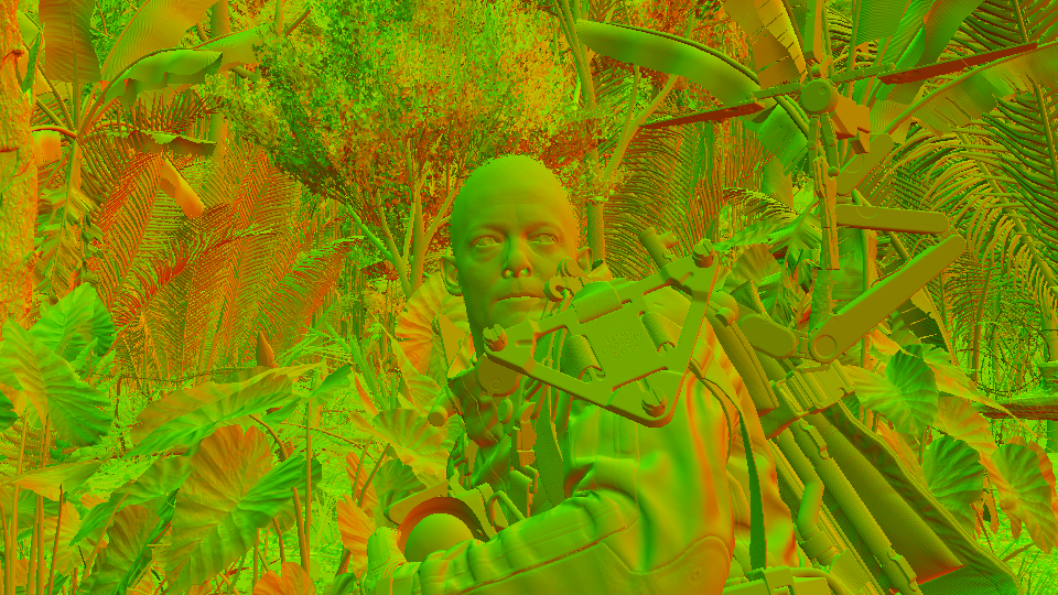
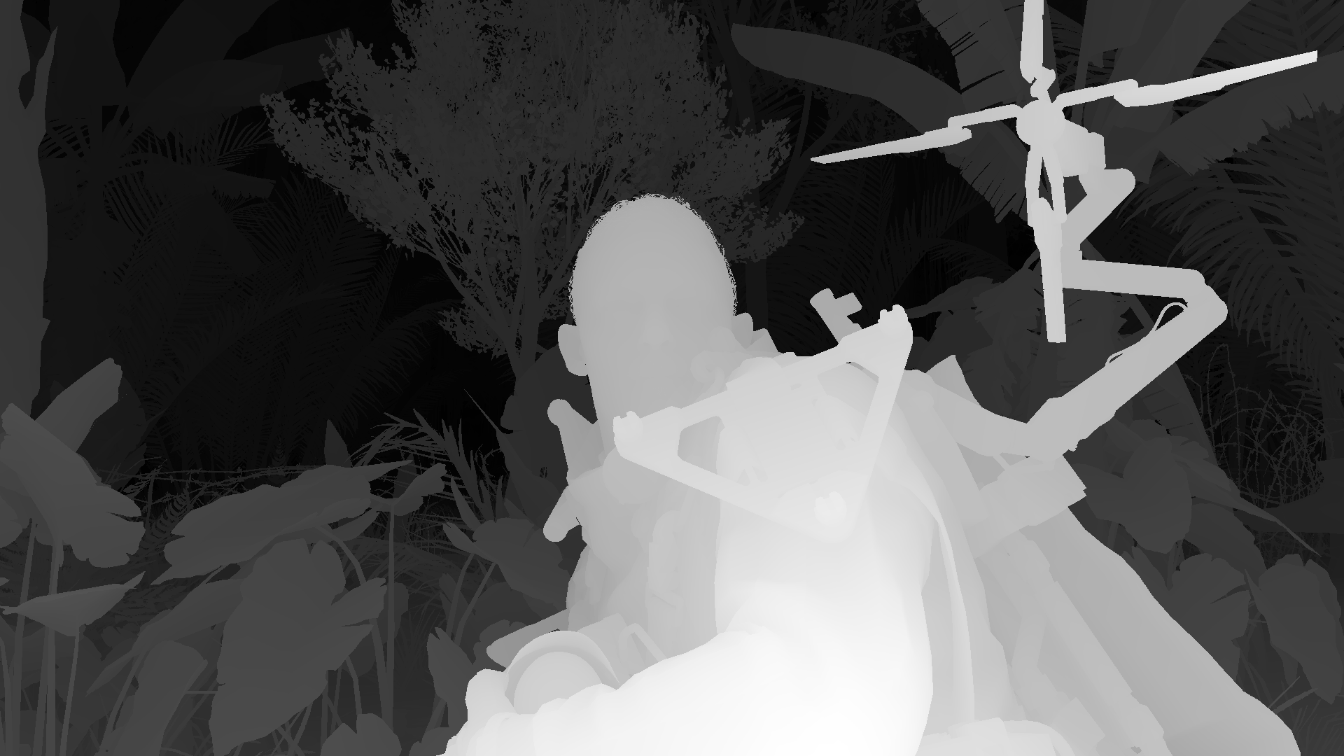
GBuffer/Deferred
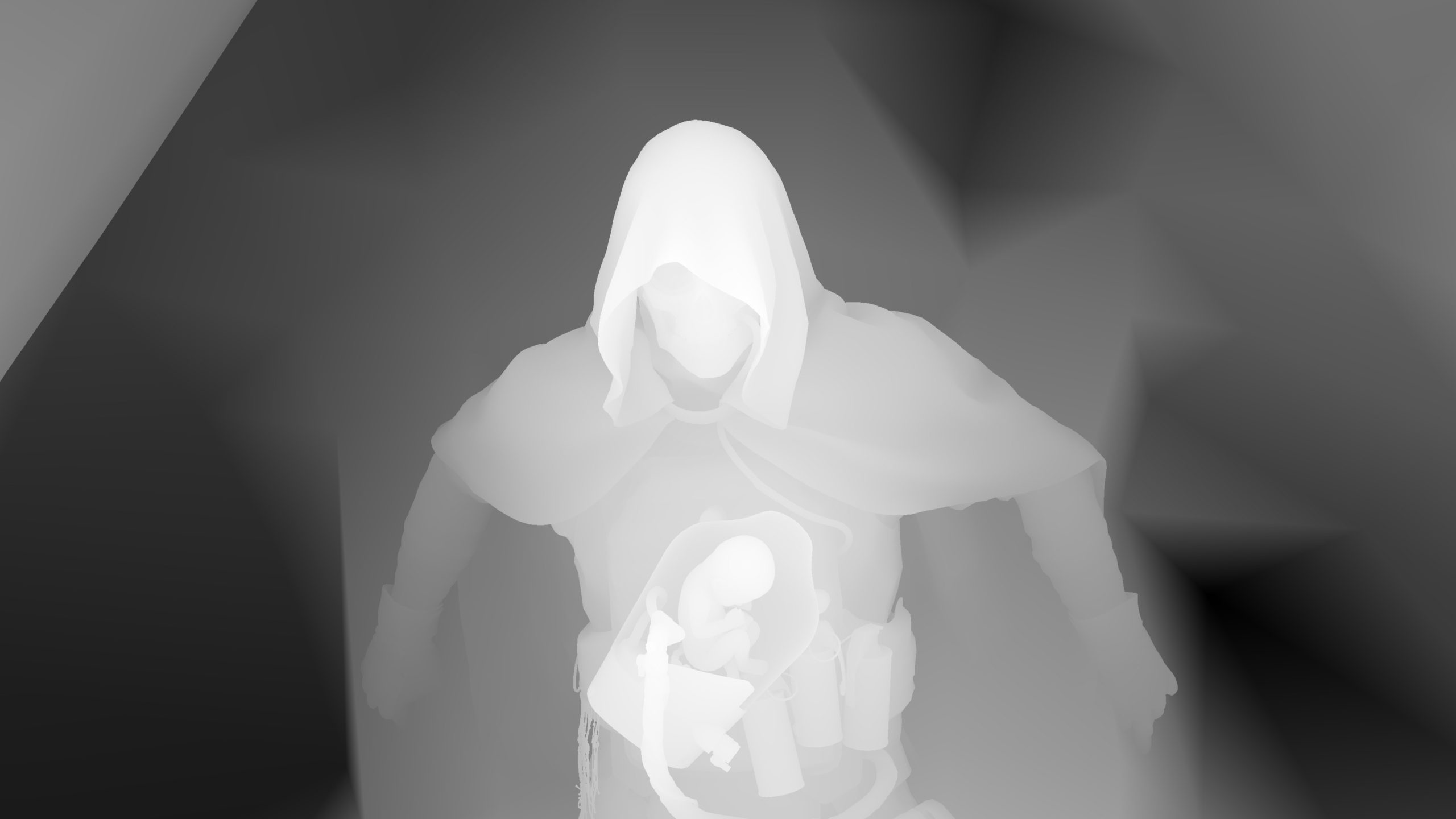
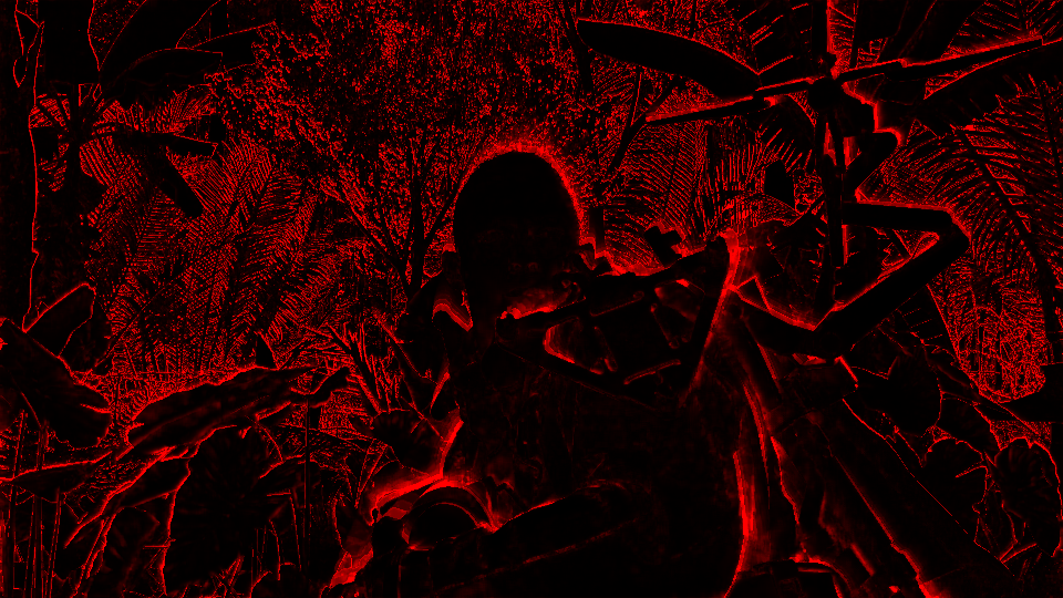
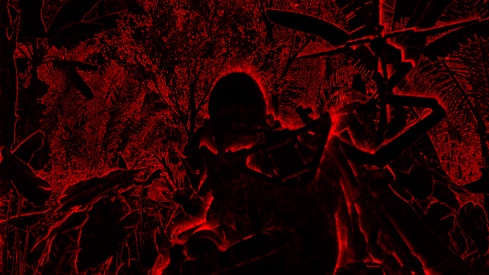
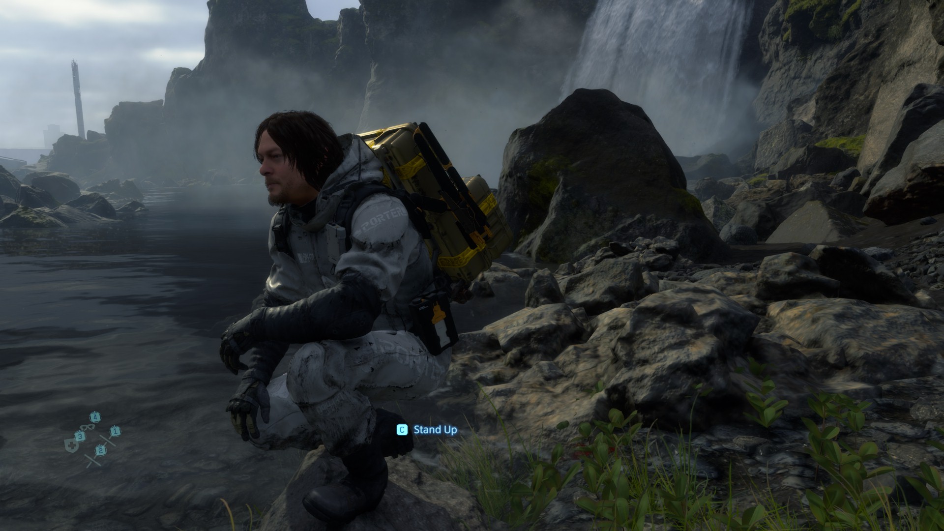
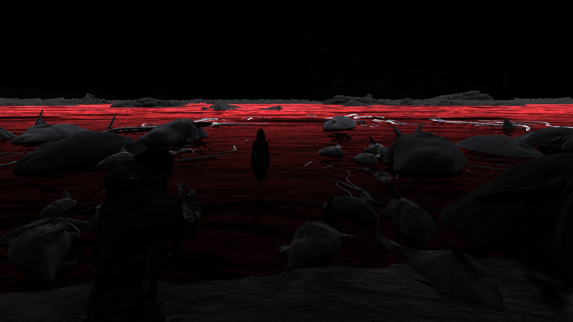
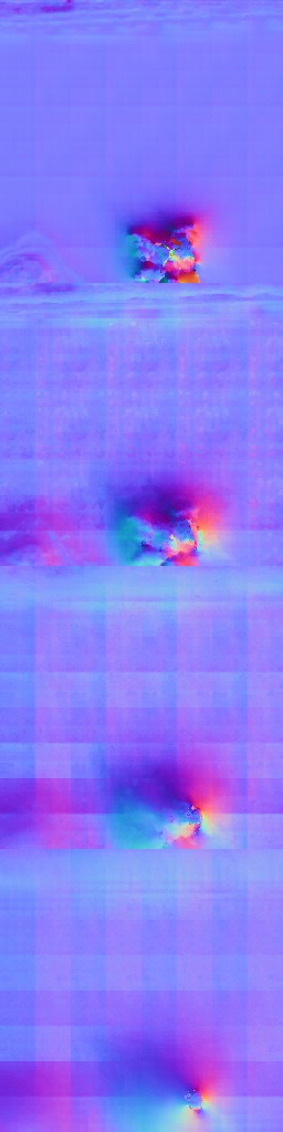
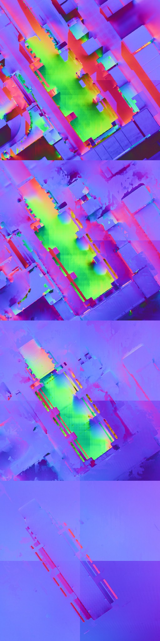
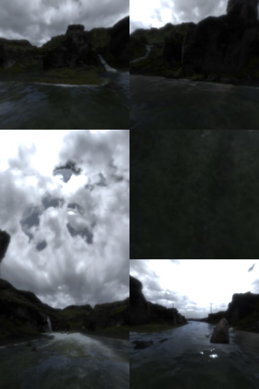
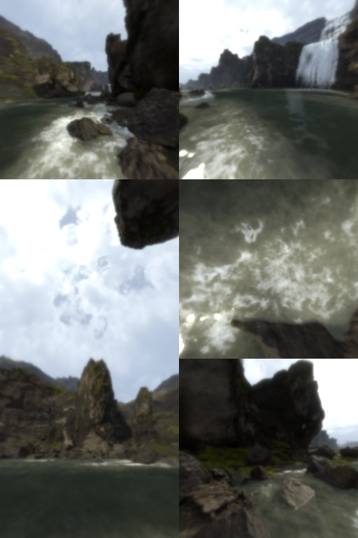
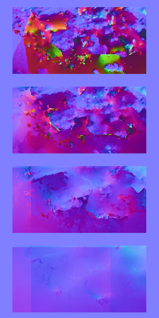
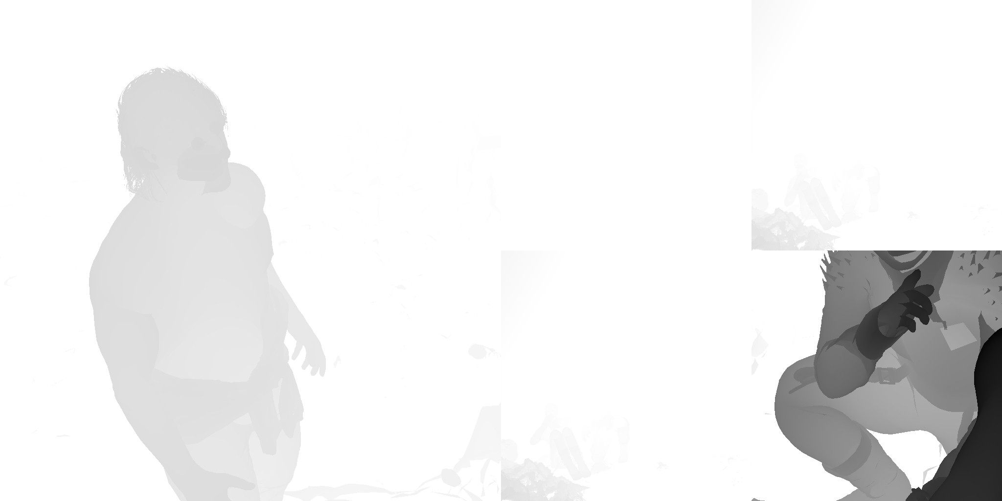
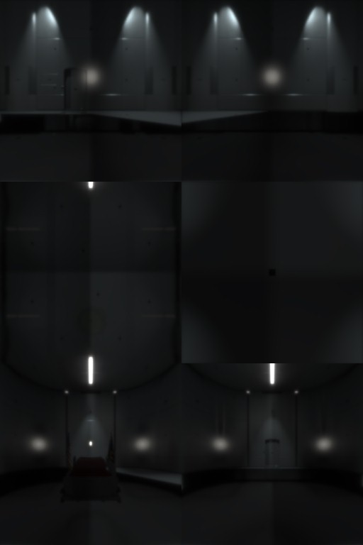
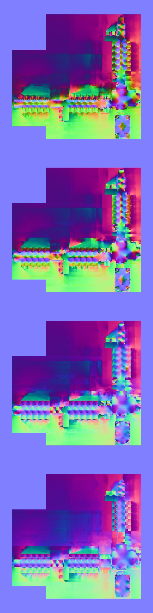
1.Depth Passes
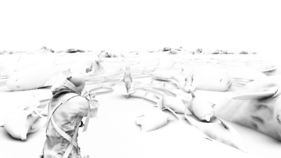
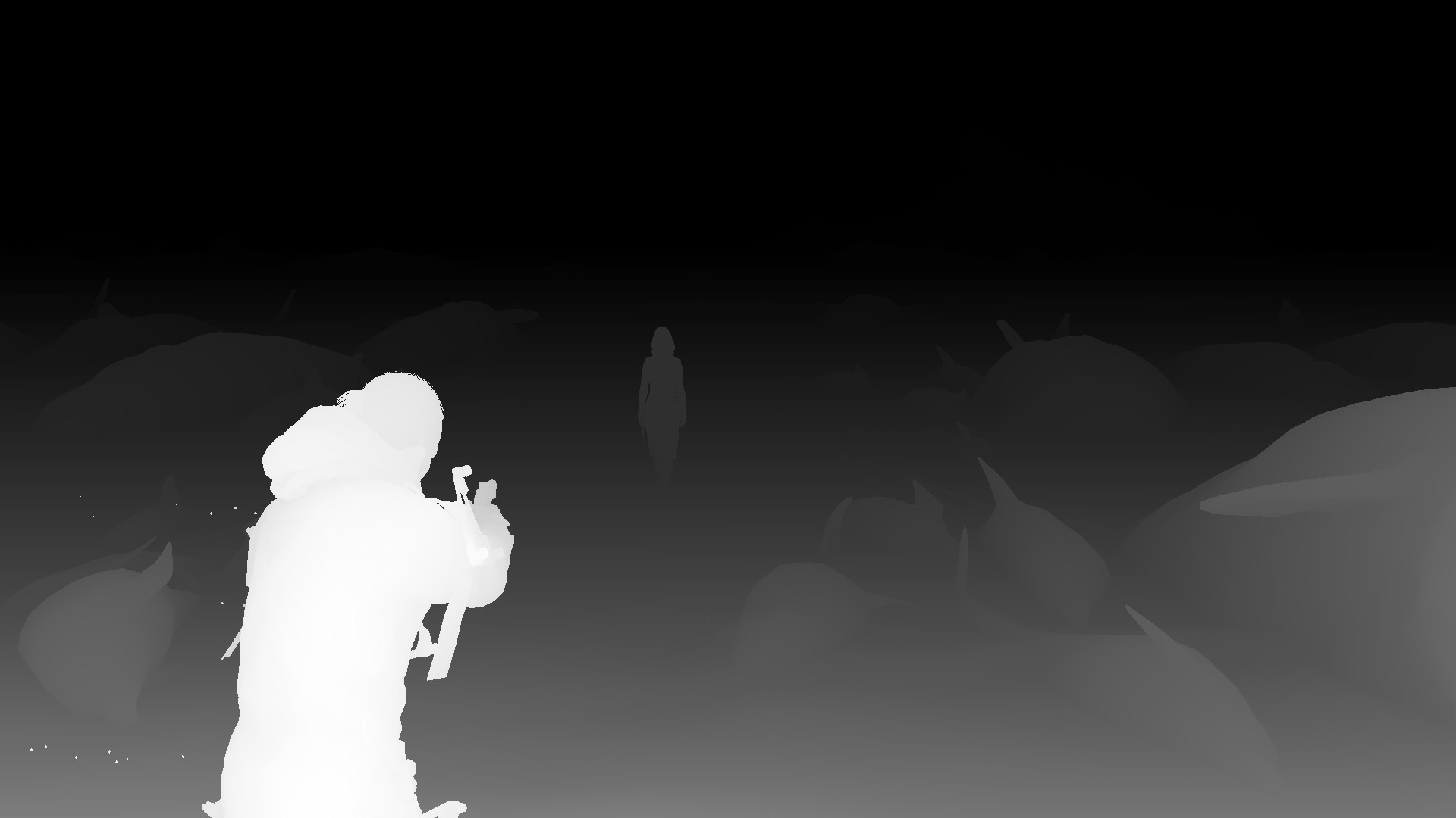
2 to 4 depth only passes (3 most of the time). Drawing to depth, step by step. It’s worth mentioning that character body is draw last most of the time. But not here..not during the depth passes (strange!)
Several draws are utilizing the ForceFields data (from earlier compute) to affect the draw for “some” meshes, such as hair, strands, grass & tree branches.


At the bottom is the final Depth image after even the Color passes are all completed
The takeaway is that, during those dedicated Depth only passes, not everything drawn to the Depth image
Possibly only meshes that would need some “deformation”
All are 1920*1080 (or target resolution) of the format D32S8_TYPELESS
Vertex Adjustment [Compute]
Sometimes there is compute dispatches between the different depth passes, that is used to update some positions values and possibly for the force fields.
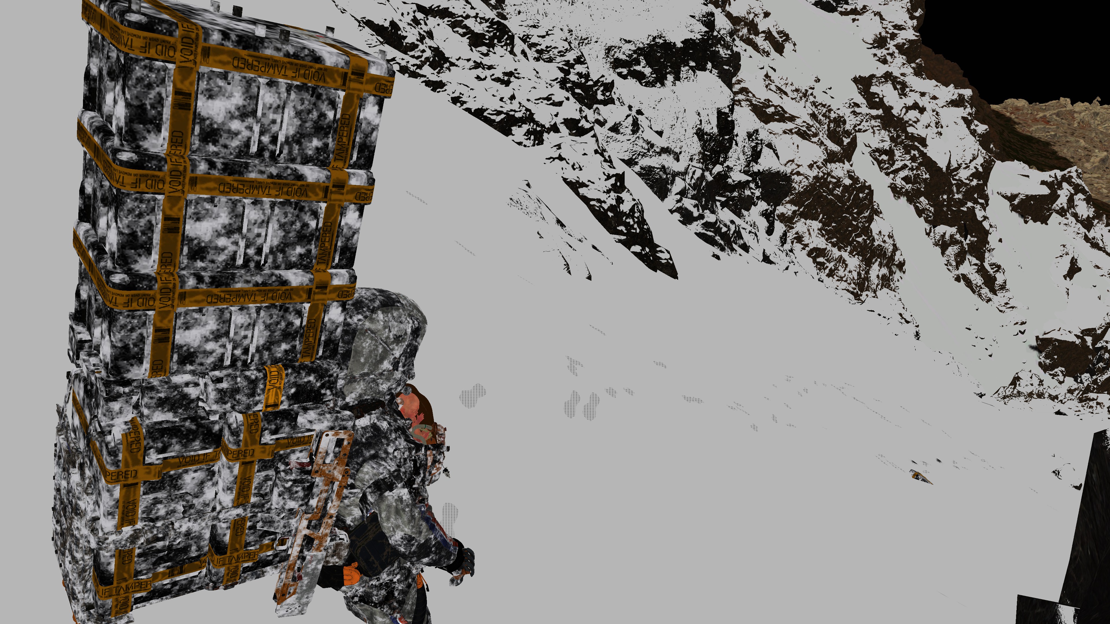
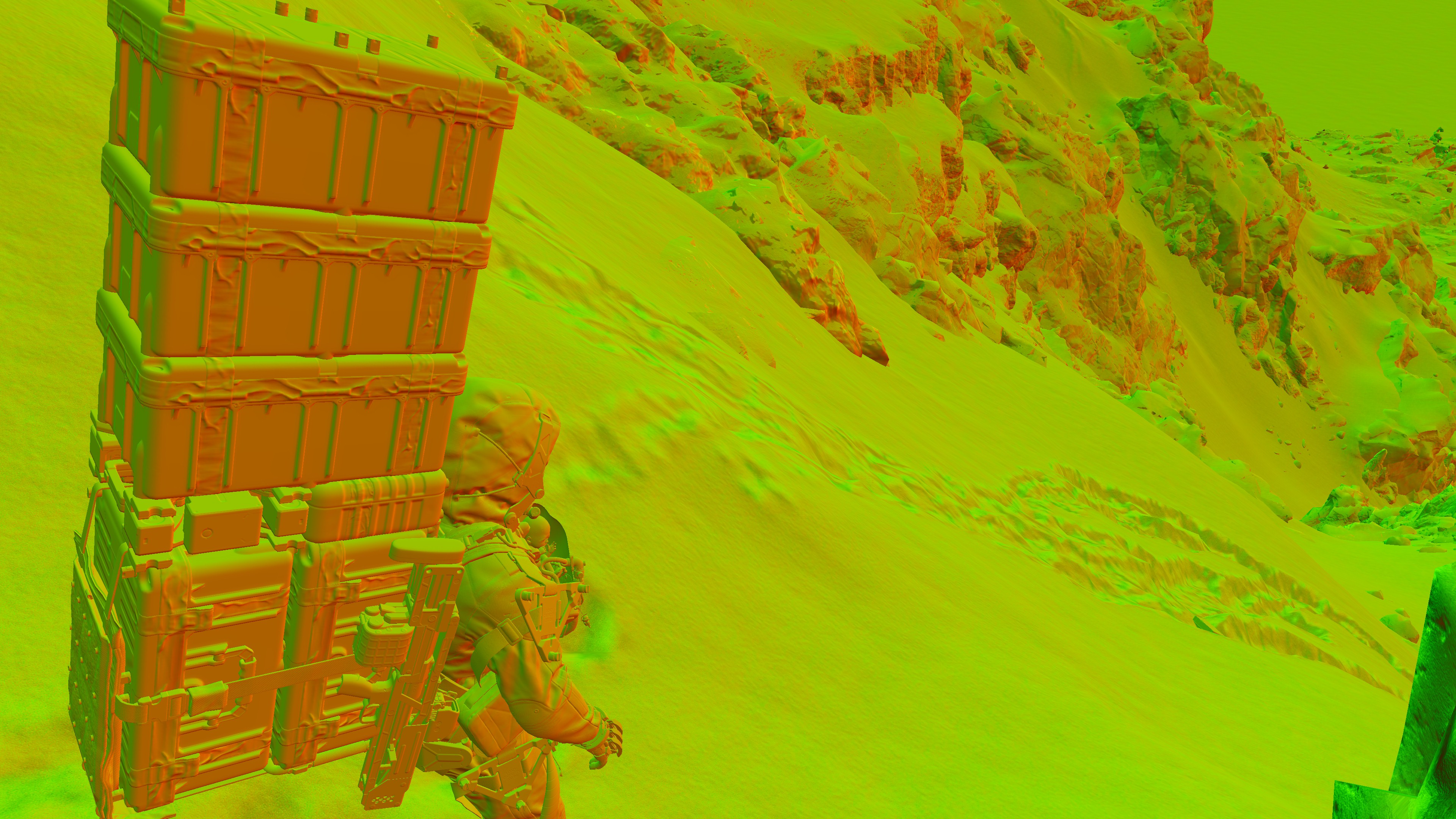
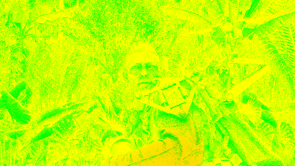
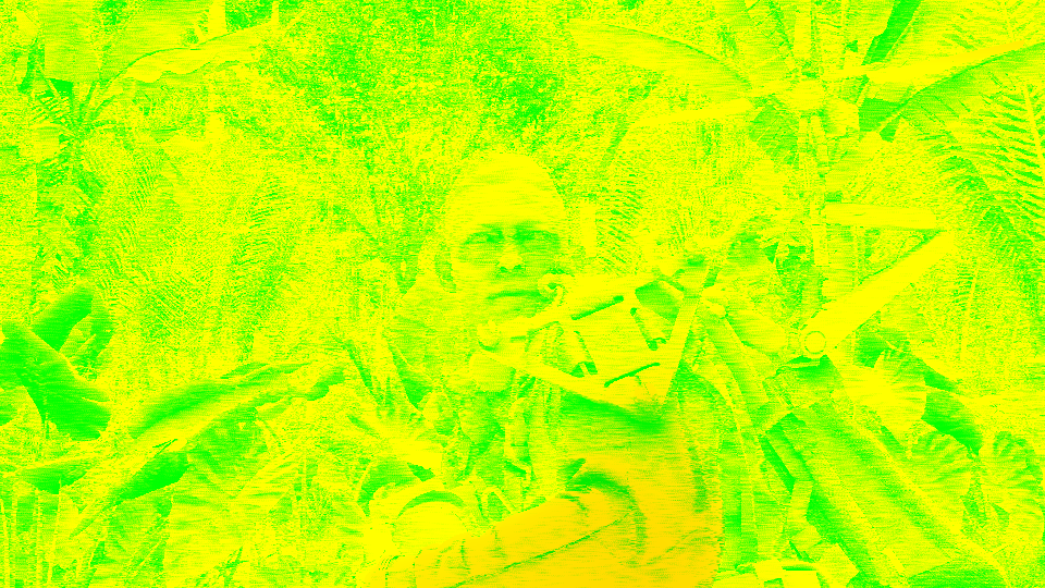
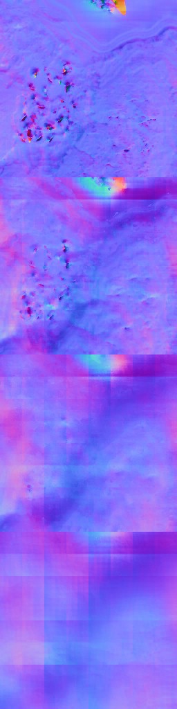
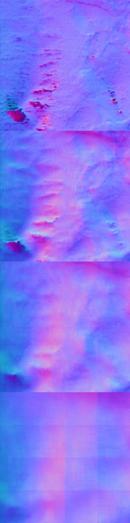
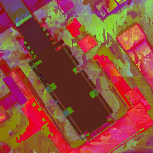
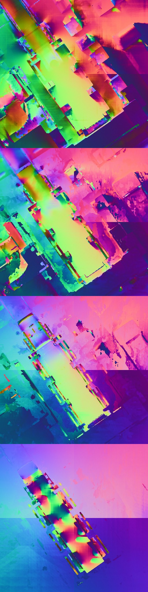
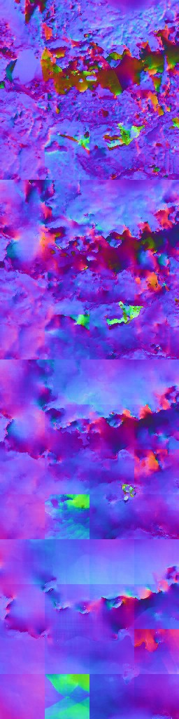
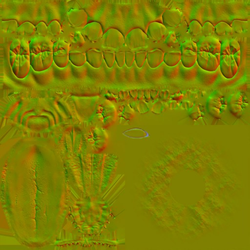
2.Color Passes (PBR)
Between 2 to 4 color passes in normal cases, but this can go up to 10 color passes for complicated or very large OpenWorld frames/views (count depends on the complexity of the frame anyways, usually it is total of 3 or 4 color passes, perhaps in cinematics where camera is a narrow angle, where many cases during gameplay reach 6 or even 7 color passes in average frames & indoors to draw the frame RenderTargets) where the deferred GBuffer is drawn to render targets. Nothing very fancy. Also at the same time, if there are remaining meshes that was not drawn to the depth in the previous depth dedicated passes (parts of Character body, and sometimes the entire character body), are drawn to depth here during those color passes before drawing the color values to the deferred rendertargets. The Depth is attached to the color passes anyways!
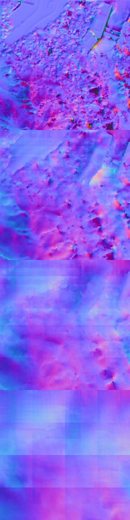
Eventually we end up with pretty standard stuff like Albedo, Normal , Reflectance, Attributes(motion + roughness) + Emissive (mostly empty) + Depth.


Why?
So, the interesting question here is why there is an isolated Depth-Only pass[es] to draw the GBuffer’s depth…or to be more accurate, to draw part of the GBuffer’s depth, where the rest of the depth is drawn within the Color pass[es]. I can’t really get the point here. It would have made more sense (for example like RE Engine) to draw the depth target at the same time during the Color Pass[es]. Because usually when there is Depth-Only pass, it is either for shadowmaps (effects) or to generate the “full” GBuffer’s depth target. Splitting here was confusing, and made no sense!
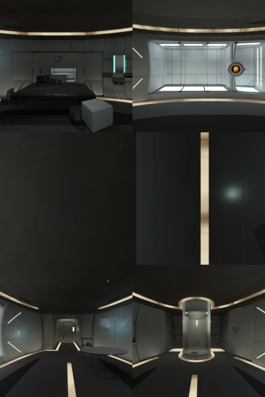
And some more frames for clarity and coverage of difference cases (indoor, night, day, …etc.)


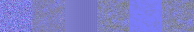
i.PBR
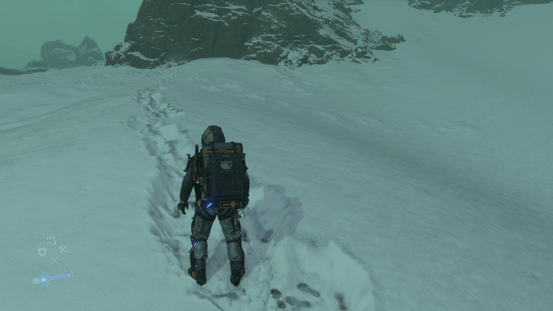
Of course it is PBR rendering, and hance some PBR textures are used to paint the GBuffer. Most of the time there is nothing out of the ordinary, but here an example of PBR mesh that is using a little more than other PBR meshes, let’s take the hoodie of Sam from the snow frame above:


The Roughness is actually holding info about Roughnesss as well as a Mask.


Not only Sam, but there are sometime Corrosion effect, that requires the mesh to get some more textures during the draw

And before leaving this PBR textures section, let’s just say, DS could do better than that.
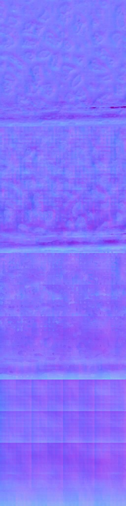
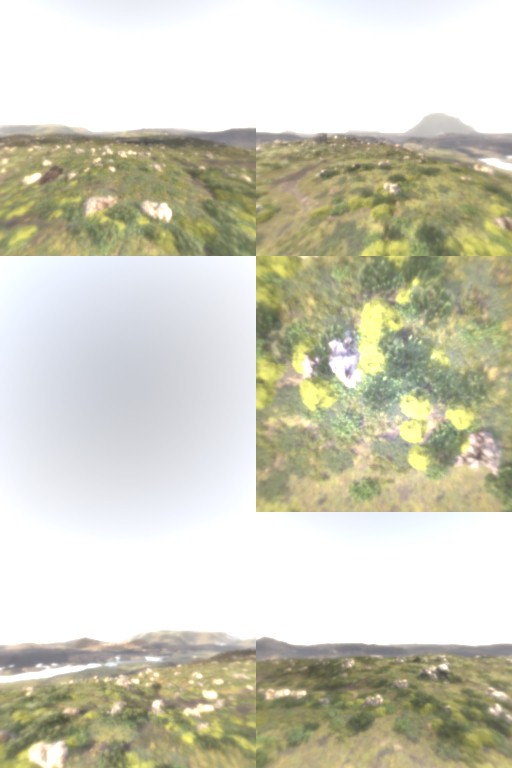
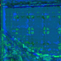
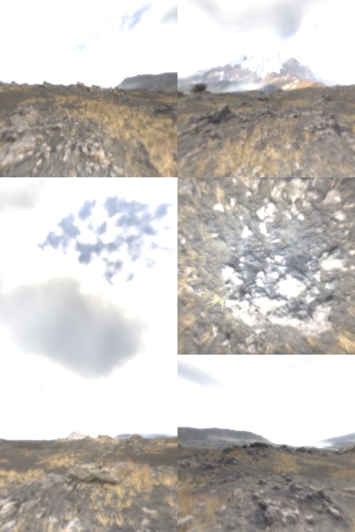
ii.Terrain & Snow
When it comes the time to draw terrain, it is done like any other terrain, just a bunch of world displacement maps (artistically made) passed to the terrain (vertex shader), so vertices can get deformed. But at the same time, the snow deformation textures (if applicable) is set to terrain during that time too, so it can modify the default artistic heigh to new height that matches the Deformation Texture. So, to complete with the same snow M thing from above, here how it is done…just one more single draw cmd!
And if you are curious about what type of displacement textures that are passed to the vertex shader to lay the foundation of the terrain, before applying the snow deformation, here are a few that are used with that exact piece of the terrain in that gif


And for the entire map landscape for example, something a little higher in quality like that is used


iii.Emissive, Decals & Emissive Decals
By the end of the GBuffer, and after drawing all the ordinary geometry, it comes the time to draw the emissive objects as well as the decals. And they are executed at that same exact order. Emissive first, then Decals. There are other times where Decals are Emissive, such as the scan effect footprints, at this case they are drawn at last.
When there is some Emissive Decals, those are painted at the very last. So you can think about it is in order as
1 – Emissive Objects
2 – Decals
3 – Decals that are Emissive
In general, the entire process can take between 1 & 2 color passes. Here are some examples


When click those, it will open higher resolution gifs, but not YT videos
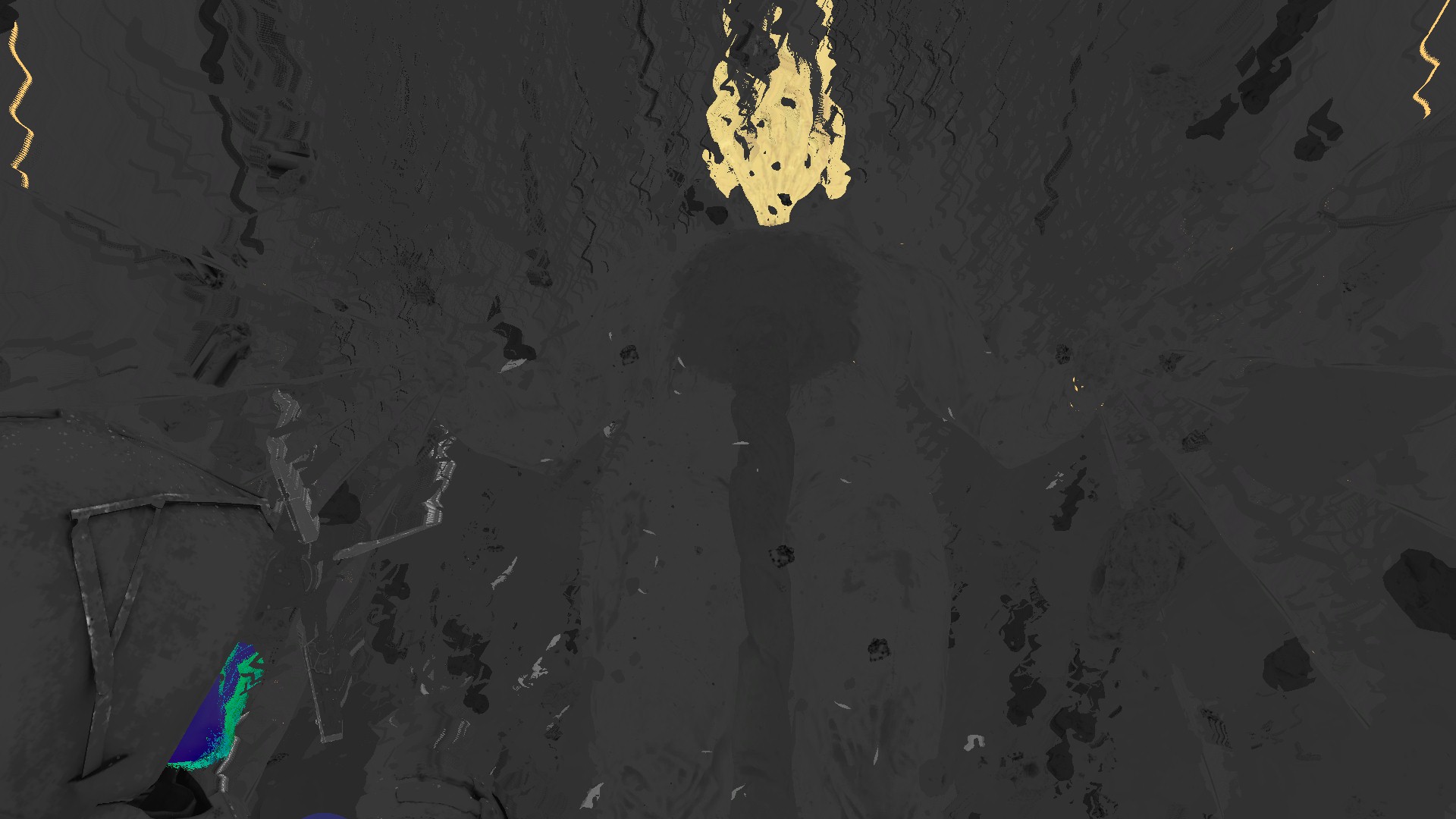
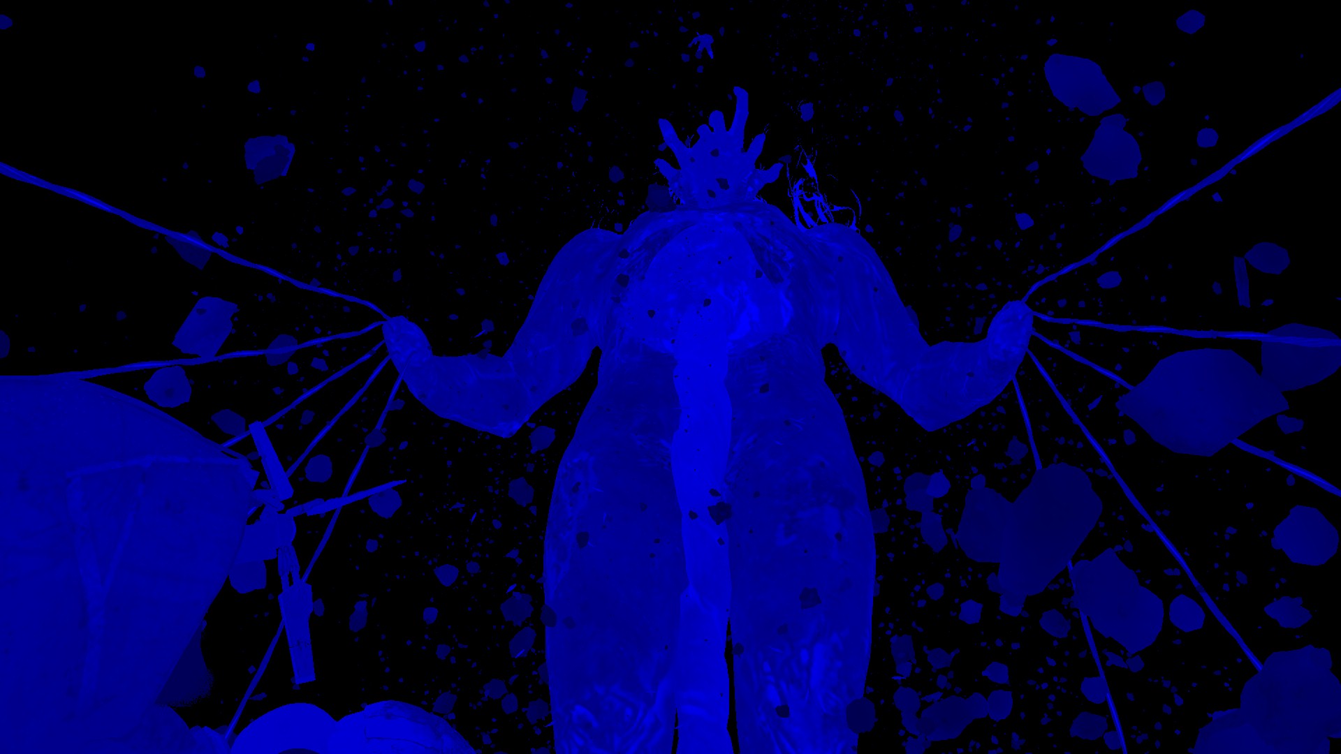
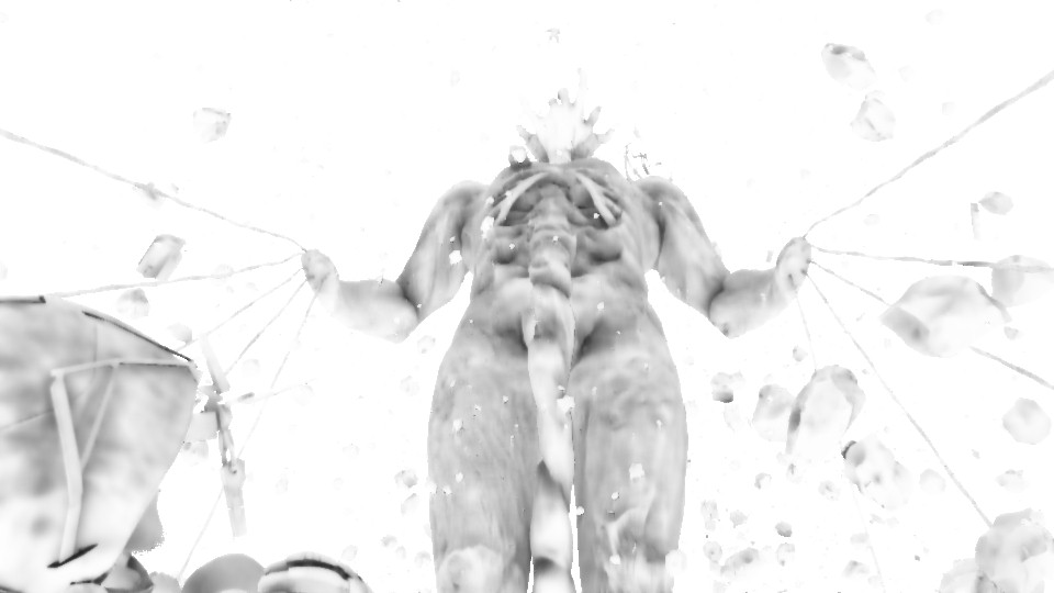
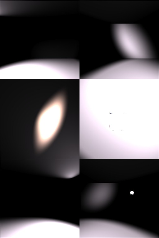
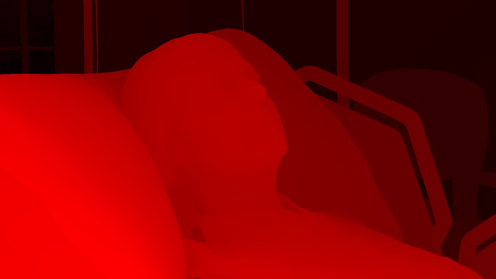
Occlusion [Compute]
i.Occlusion Capture
//TODO
ii.Occlusion Downsample
//TODO
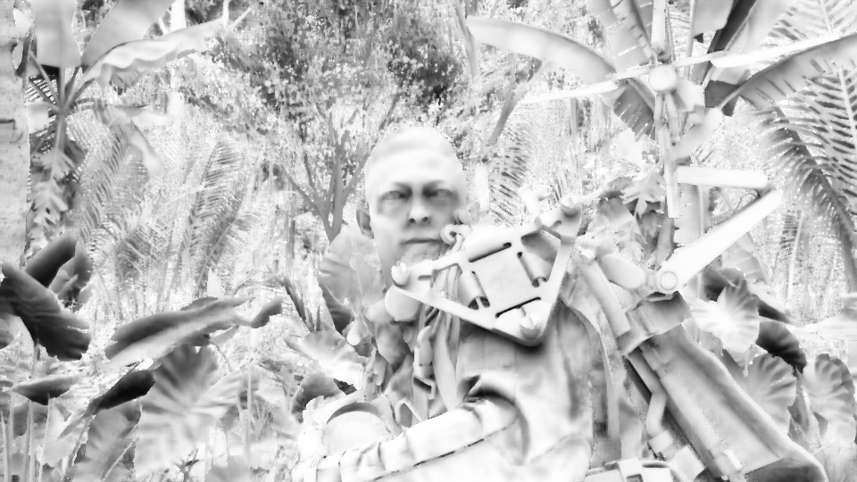
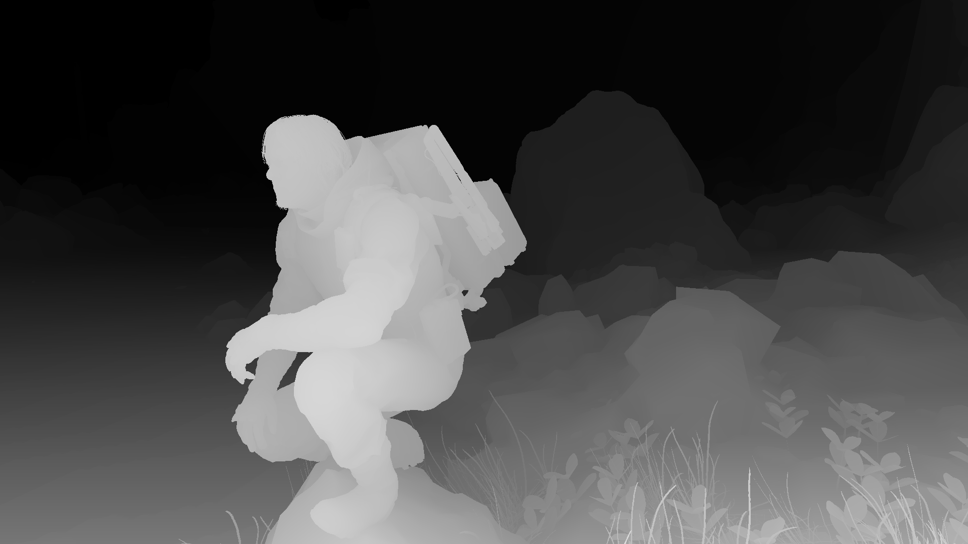
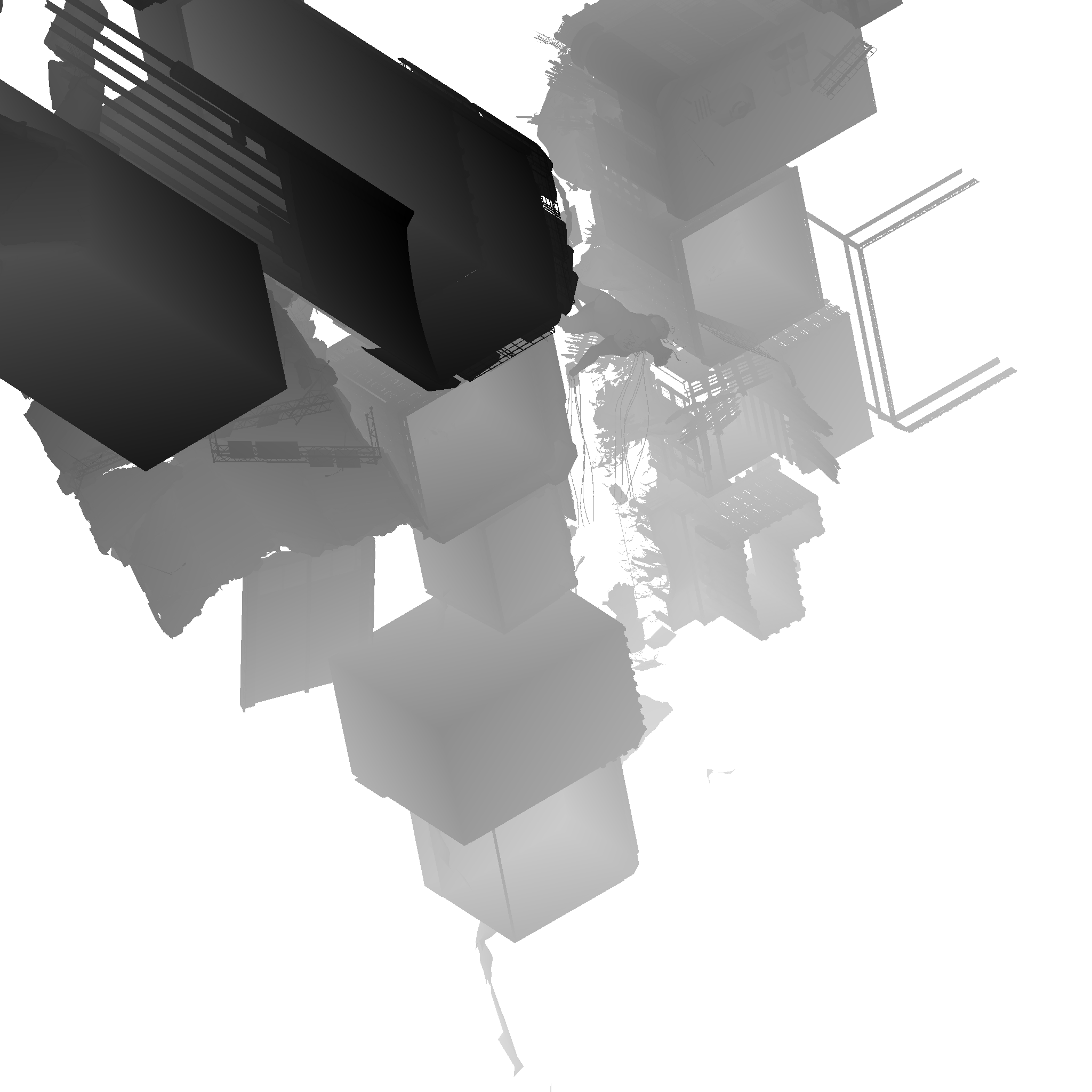
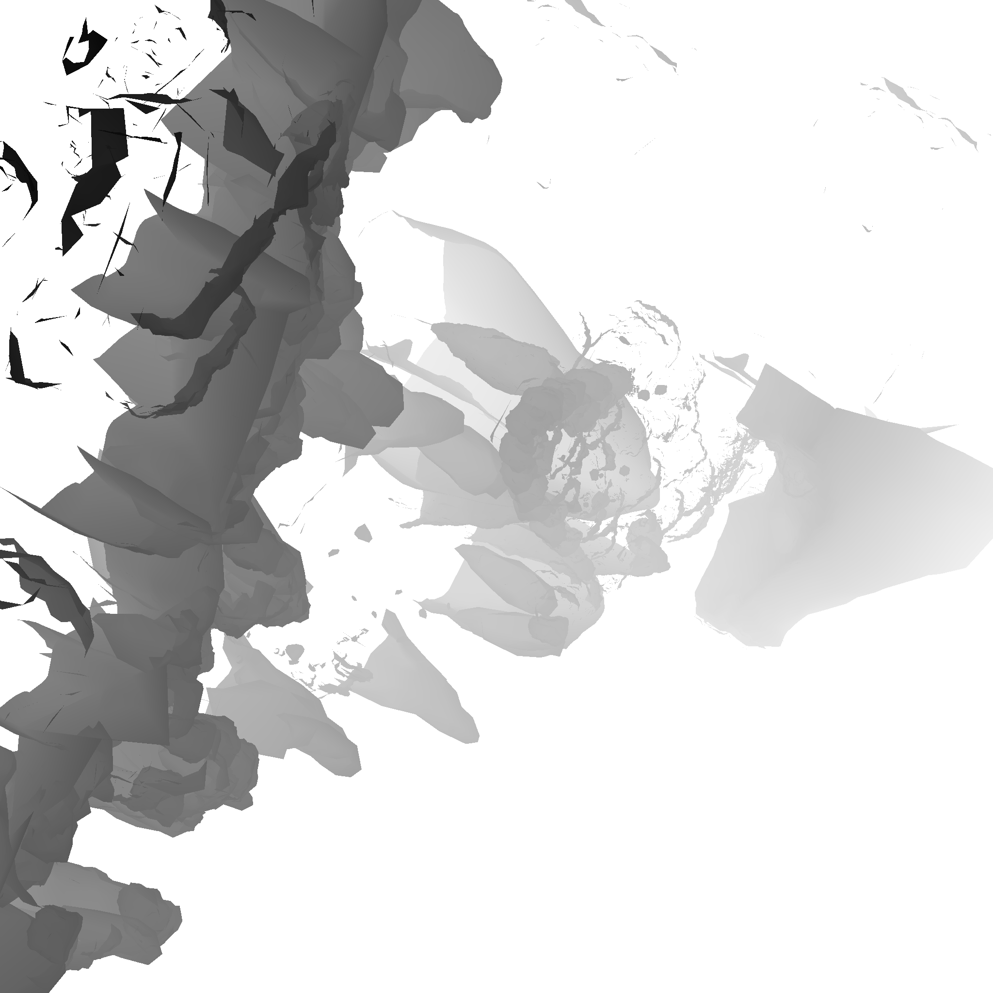
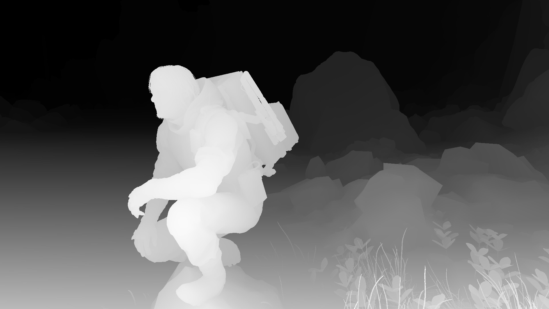
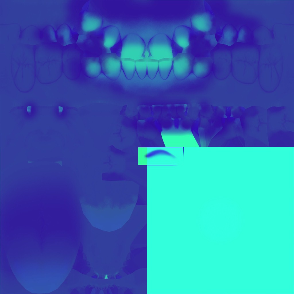
Depth Downsample
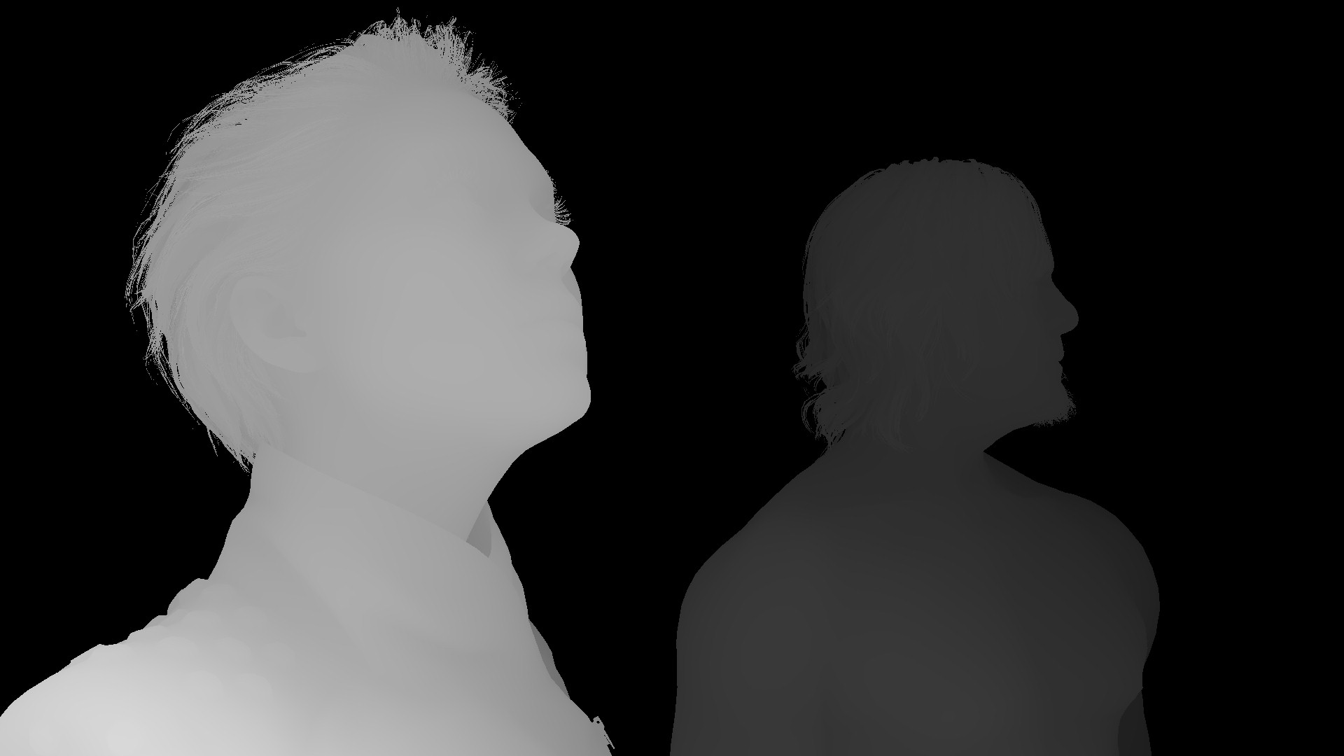
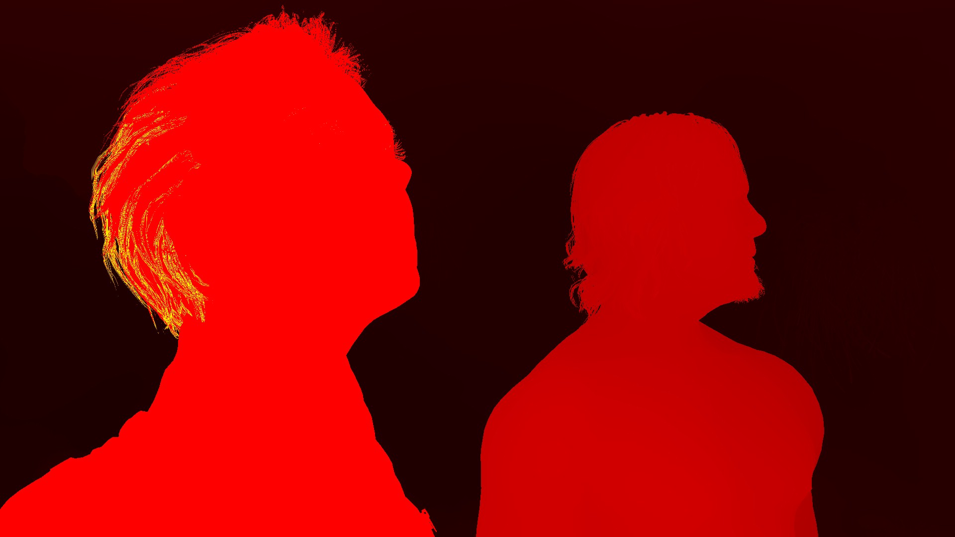
As the habit goes, downsamples of depth will be needed for quite a few things down the pipe, so it’s a good timing to prepare a 1/2, 1/4 depth versions at the side. 1920*1080 to 960*540 to 480*270
Not only that, but also separate min depth and max depth into their own rendertargets (1/2 res ones)
HalfResMinDepthTexture and HalfResMaxDepthTexture
All that happens in an off-screen quad, or to be exact, off-screen larger-than-viewport triangle (yummy, it’s the way i like)
Copy & Clear
Yet another one!
GBuffer Downsample [Compute]
Same as what been done previously with the depth, except that this time it’s half-res only, and it’s done in compute for pretty much all the GBuffer targets (Color, Attributes, Depth again).
This step seem random, and useless, and perhaps a remains of some obsolete code, as i see it is not necessary, and the outputs not utilized in any way. Not to mention that the outputs are solid black rendertargets.
Prepare Lookup Texture [Compute]
//TODO (Examples)
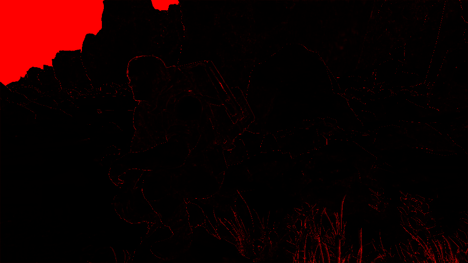
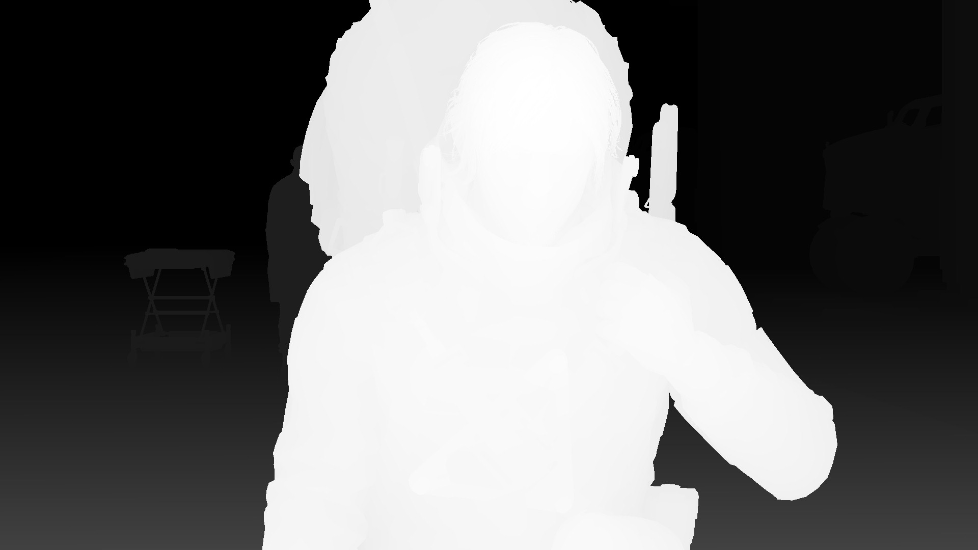
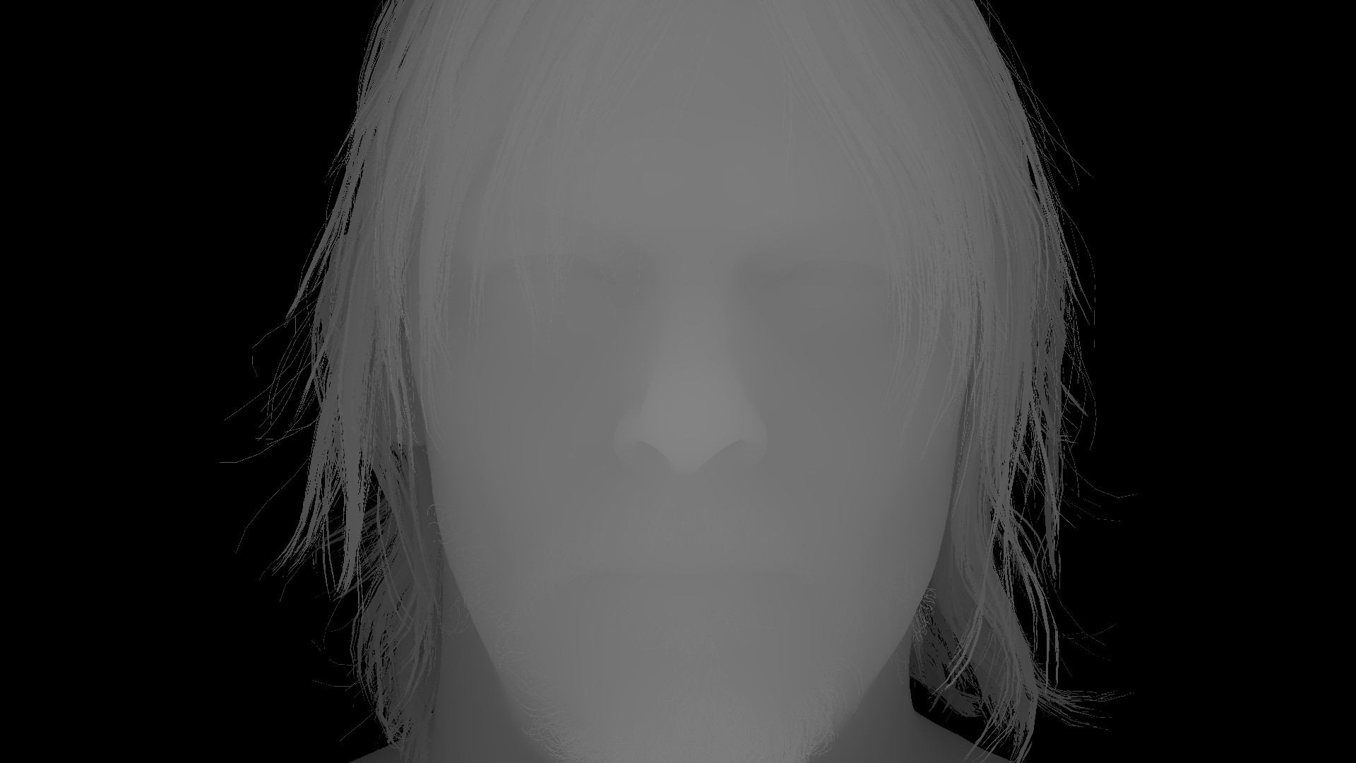
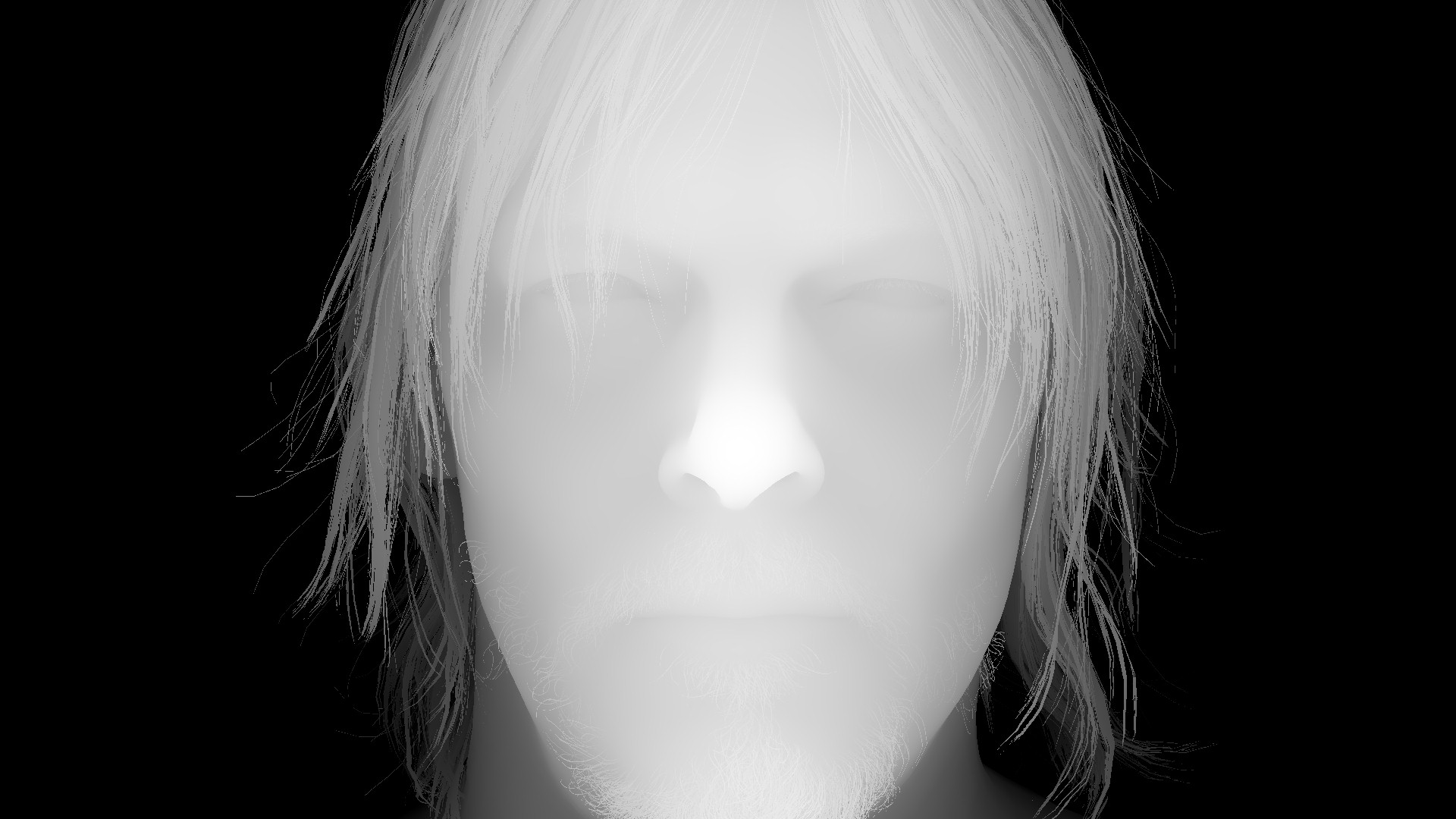
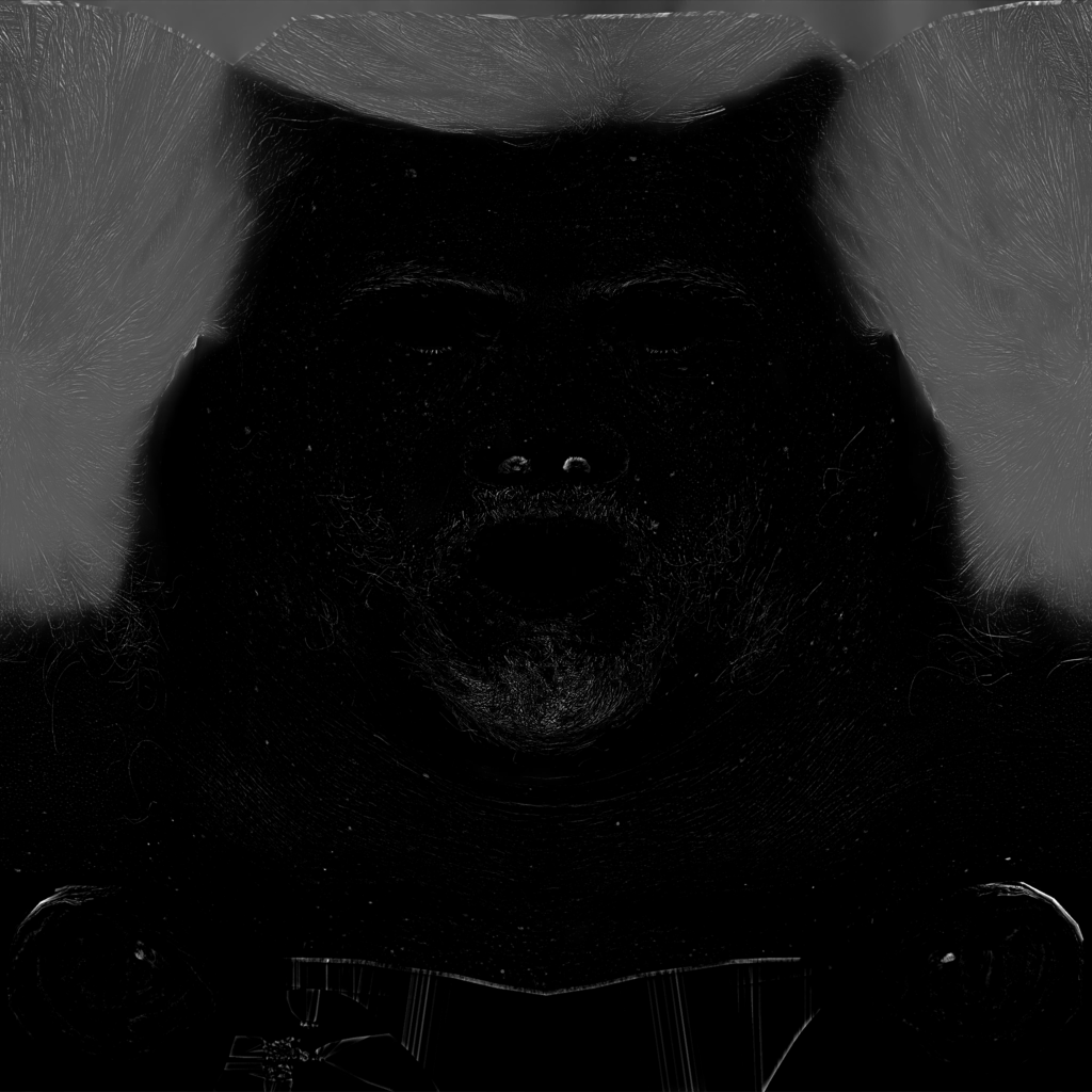
SSAO
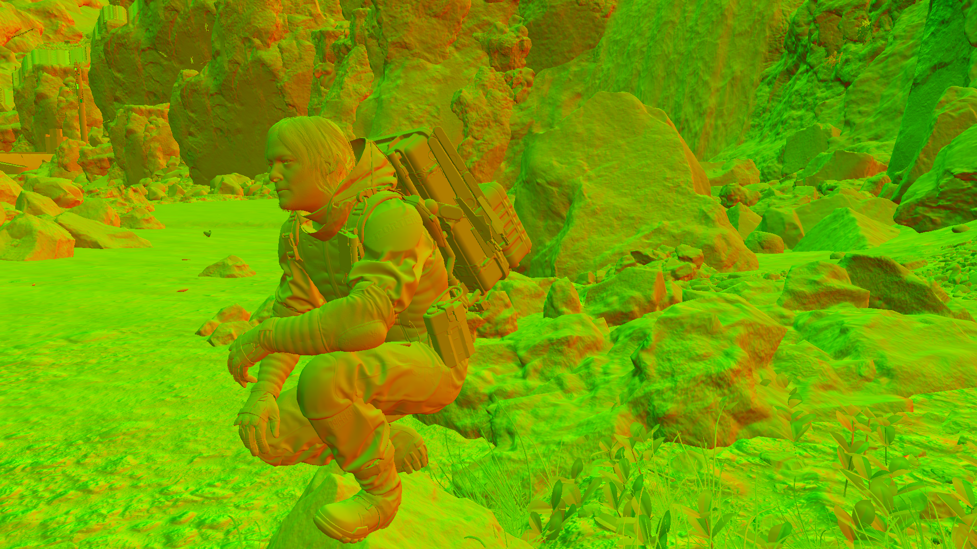
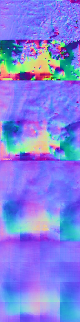
1.Downsample Normals
Take a full frame GBuffer’s normal target, and scale it to the 1/2 with a slight format change. So at this case from 1920*108 to 960*540

2.Generate SSAO
using the previously downsampled GBuffer’s normal, in addition to the Depth and a sample depth LUT, The frag shader run to generate a noisy SSAO image with the same size as the input Normals rendertarget.


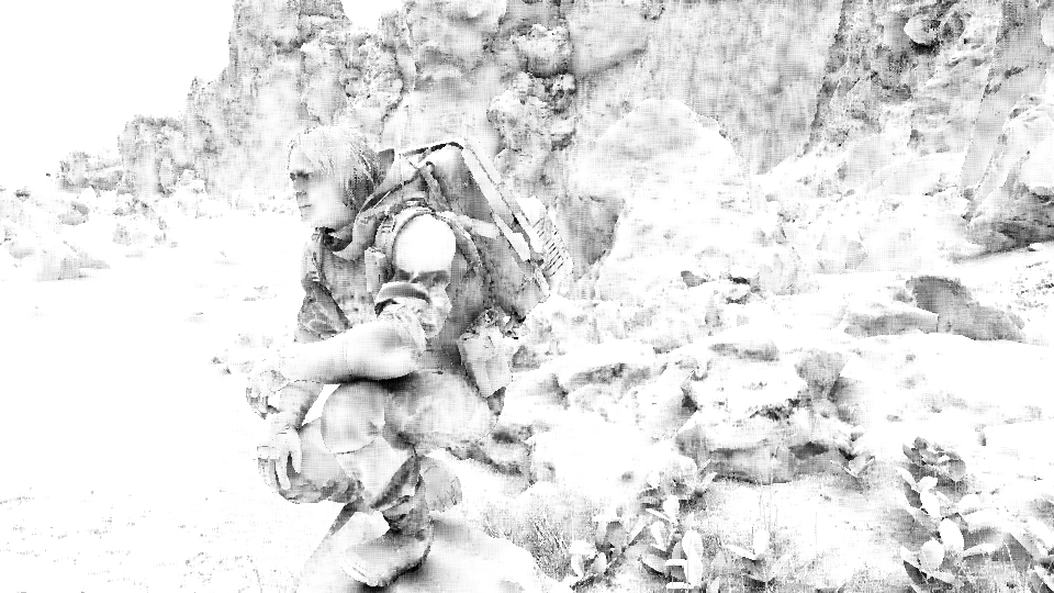
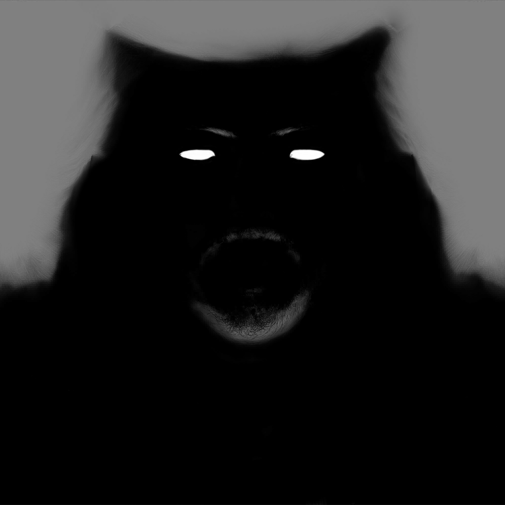
3.Blurring & Smoothing SSAO
Couple of invocations to the blurring frag shader, starting by Horizontal blurring, followed up by Vertical blurring by using the normals (downscaled one) as well as the current noisy SSAO image.
Blurring Params
struct mInUniform_Constant
{
	float4 mDirSize;
	float4 mParams;
}
i.Horizontal SSAO Blurring
ii.Vertical SSAO Blurring

iii.Accumulate Smoothing SSAO
When that done, using the previous frame’s data such as the SSAO image & motion vectors of the previous frame, a once more blurring step takes place in order to generate as smooth as possible SSAO image.


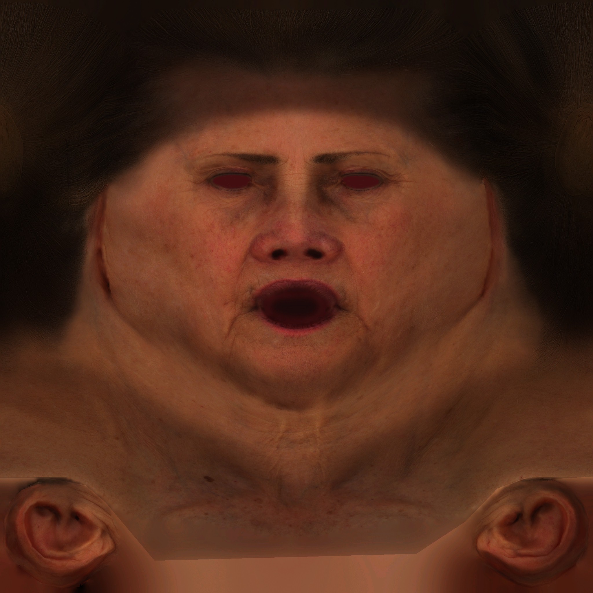
4.Transfer SSAO
Now come to the weird thing. This last step of extra blurriness, is taking place in two steps, previously you’ve seen the 1st step, here is the in & out of the 2nd step.


As you can see, the output of both steps is “exactly” the same, it’s more of transferring except it is not actually a “transferring” call. What happens here is that the DrawInstanced() call, at first issued to draw as a fullscreen TRIANGLE (larger than the viewport of course), and then using the output of that call, to issue another DrawInstacned() where it issues as a fullscreen QUAD. So it’s little strange, why not draw on the target surface regardless what it is from the first time?! Output of both steps is exactly the same, it’s just re-drawn! This could be due to some changes before shipping, or due to deprecation for some AO library,…etc. But all in all, yes SSAO quality looks good in that game, but that tiny thing can improve performances even in μs.
Not to mention, that each of the last two steps (that have the same output), each of them using totally different vertex descriptions!
Triangle Vs Quad Vertex Description
POSITION   R32G32B32_FLOAT           0
TEXCOORD   R32G32_FLOAT              12
POSITION   R32G32B32_FLOAT           0
COLOR      R32G32B32A32_FLOAT        12
TEXCOORD   R32G32_FLOAT              28
Where the 1st one is used for vertcies drawin the Triangle in Step 5 (the SSAO smoothin), the later one used for the 6th step (transferring). So why?! What is even the need for some vertex color data here?!
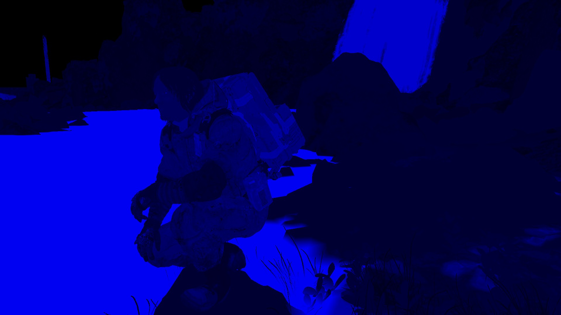
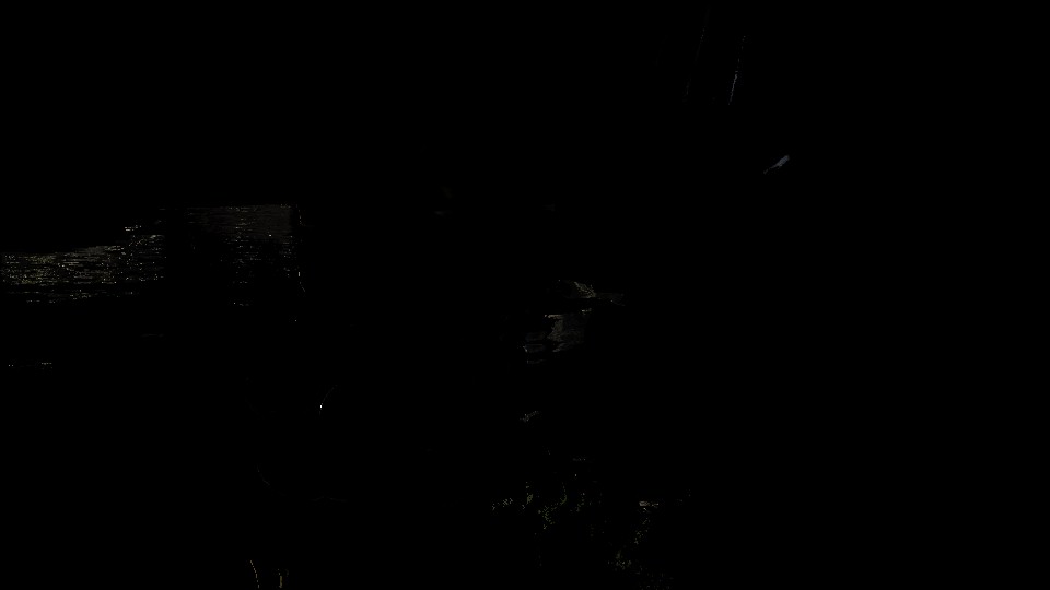
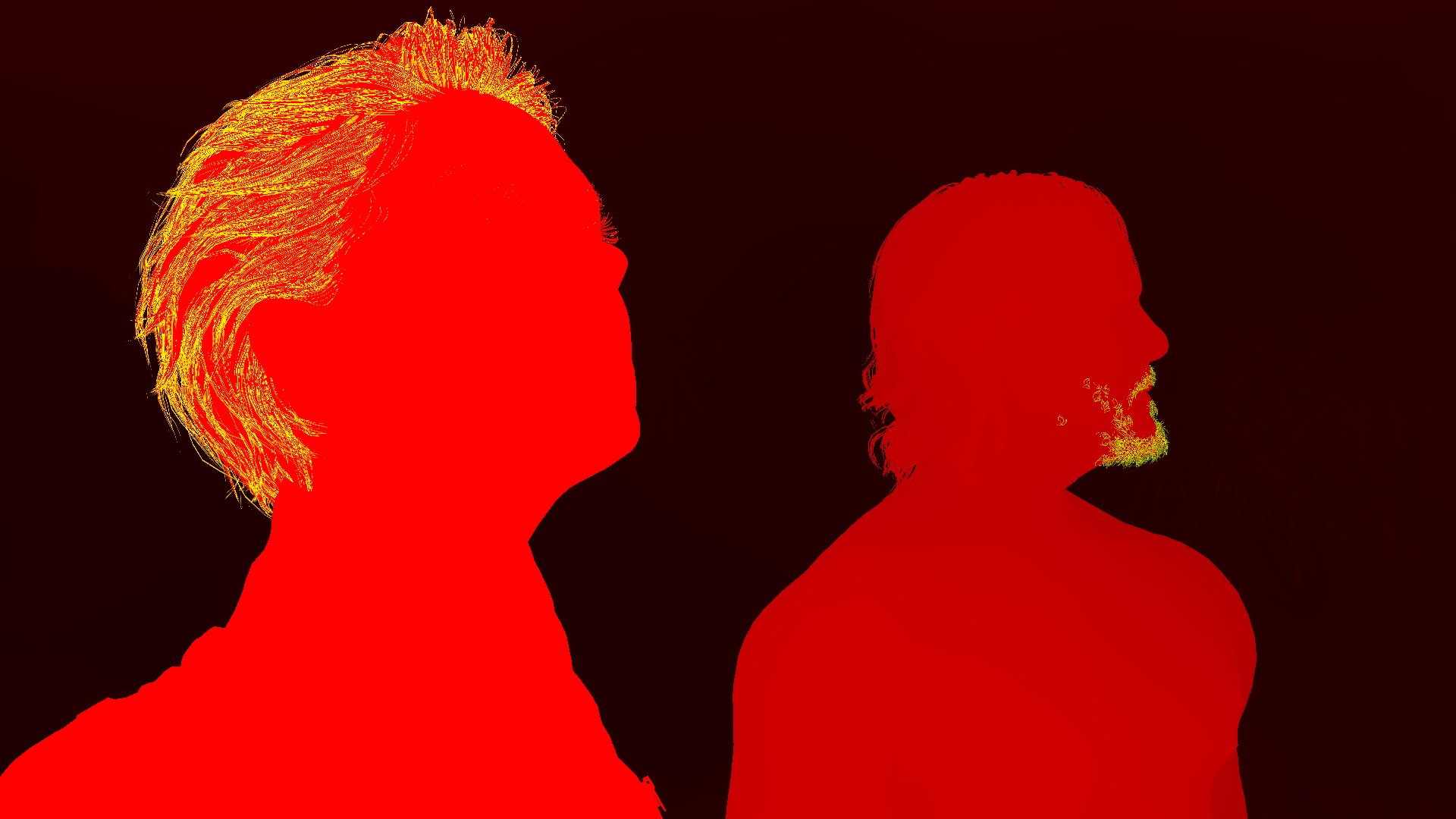
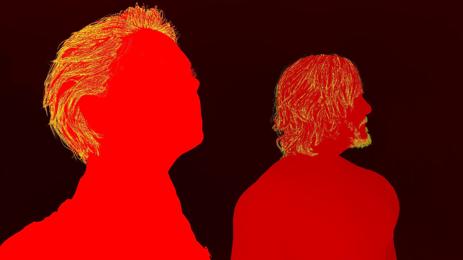
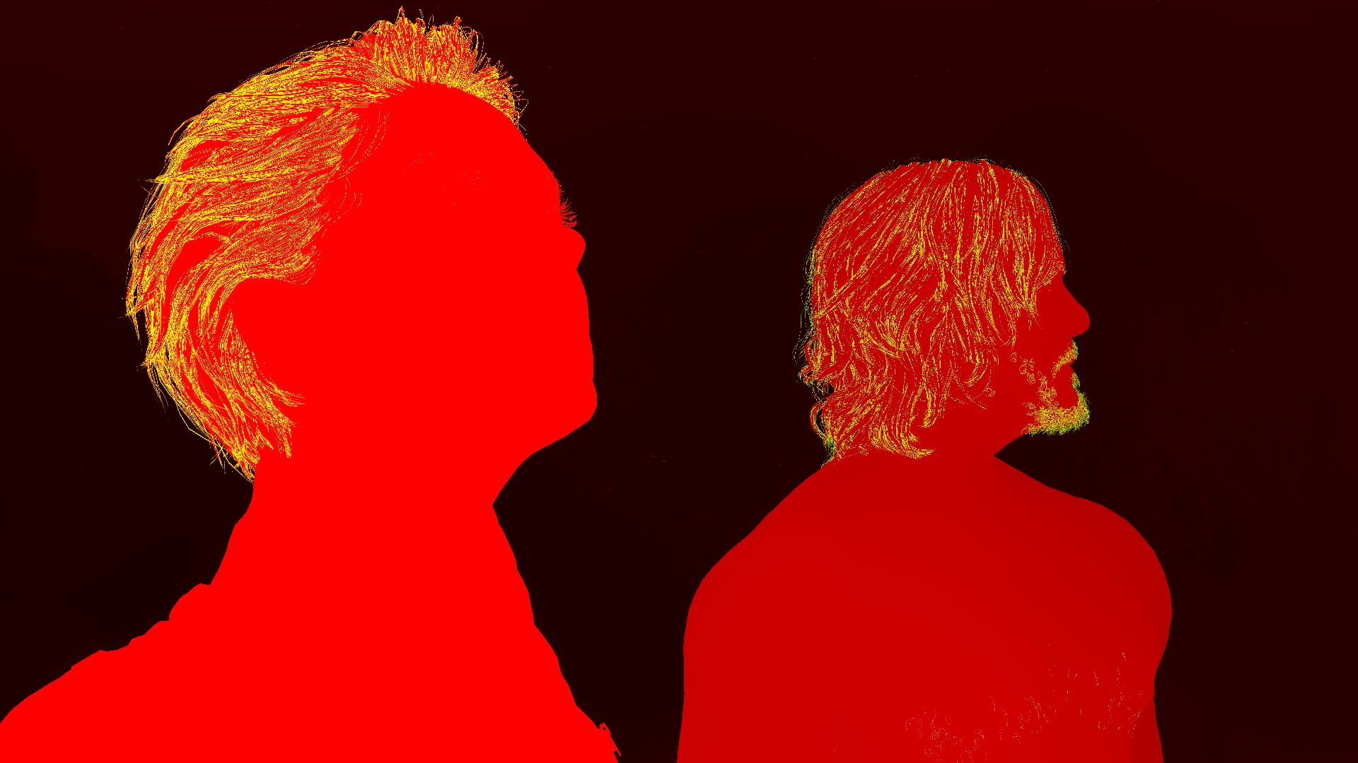
And of course, channel utilization is good. It’s an RG img format, but after all when saved to disk and dropped here in browser, it’s has to be a RGBA, so here is a breakdown (RGBA even though it’s just RG), just in case…


But still, this makes not sense to have 2 channels for SSAO instead of 1 at the same time the Linear Depth (single channel) rendertarget remains to the end of the frame!
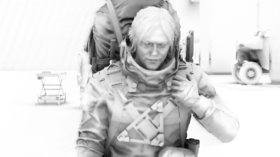
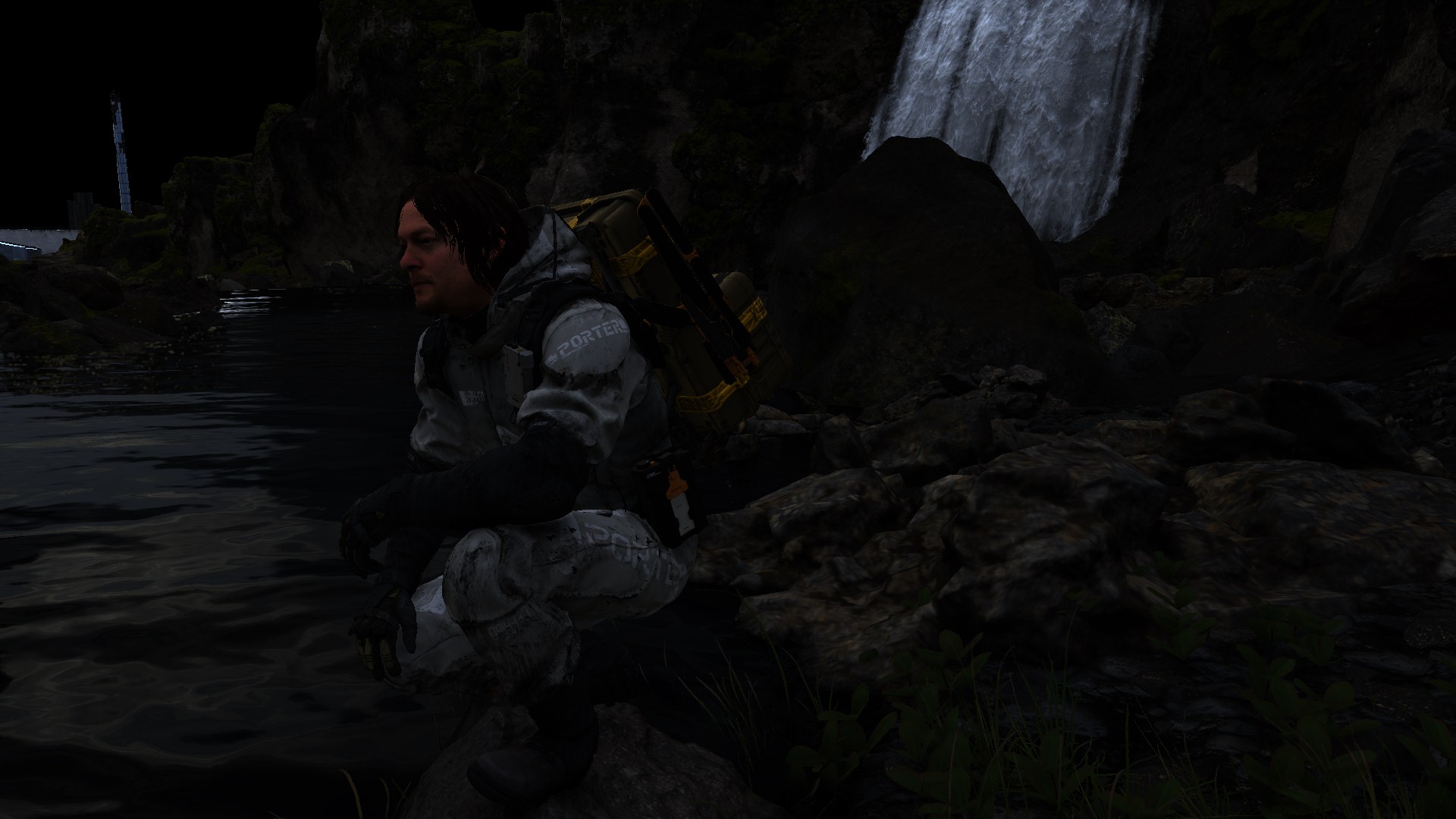
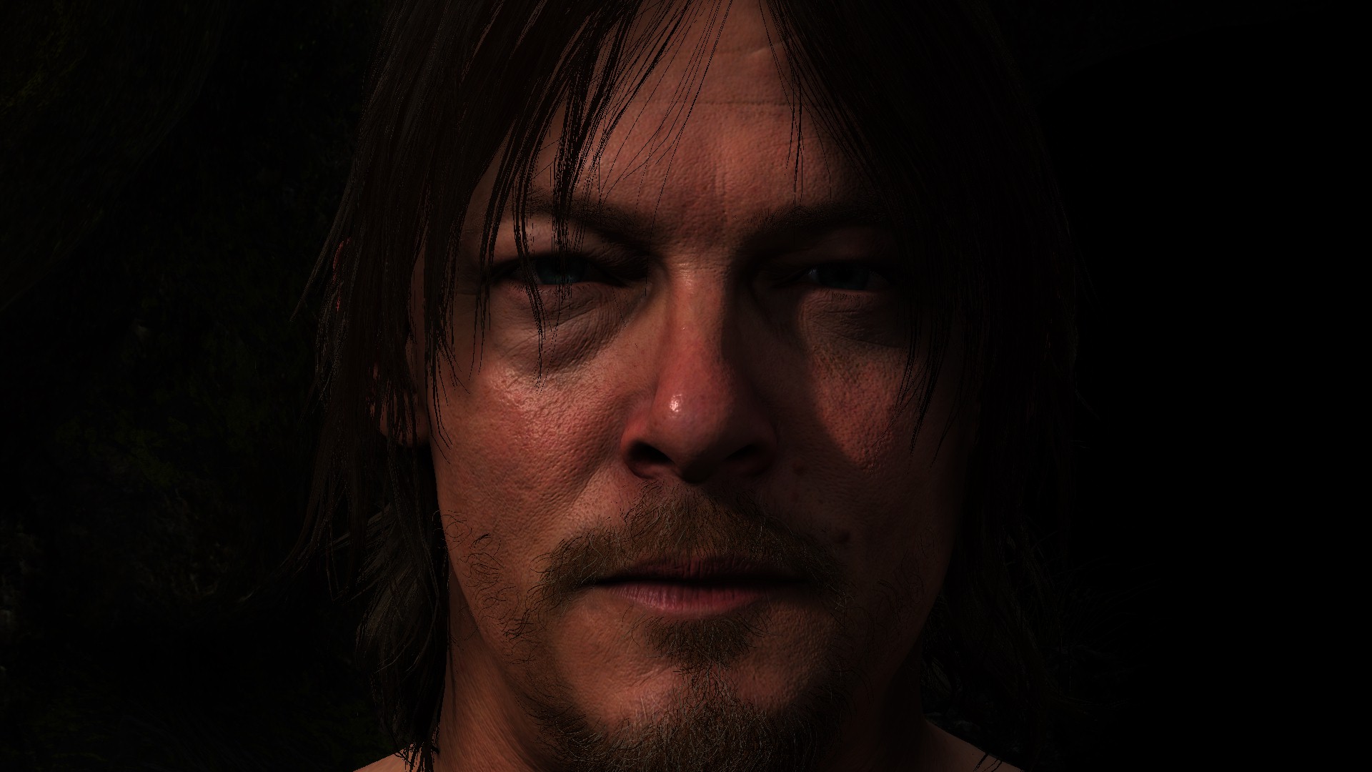
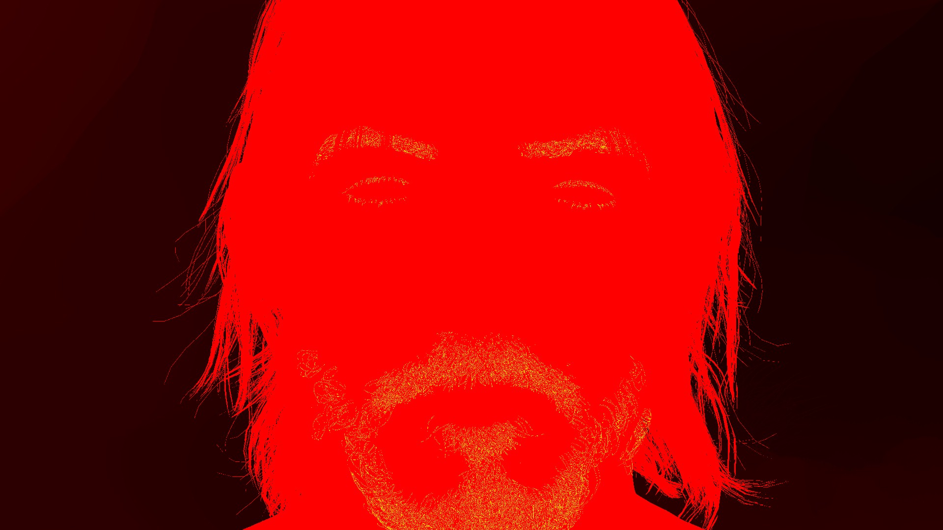
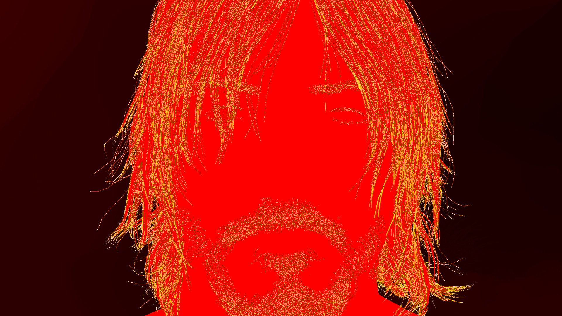
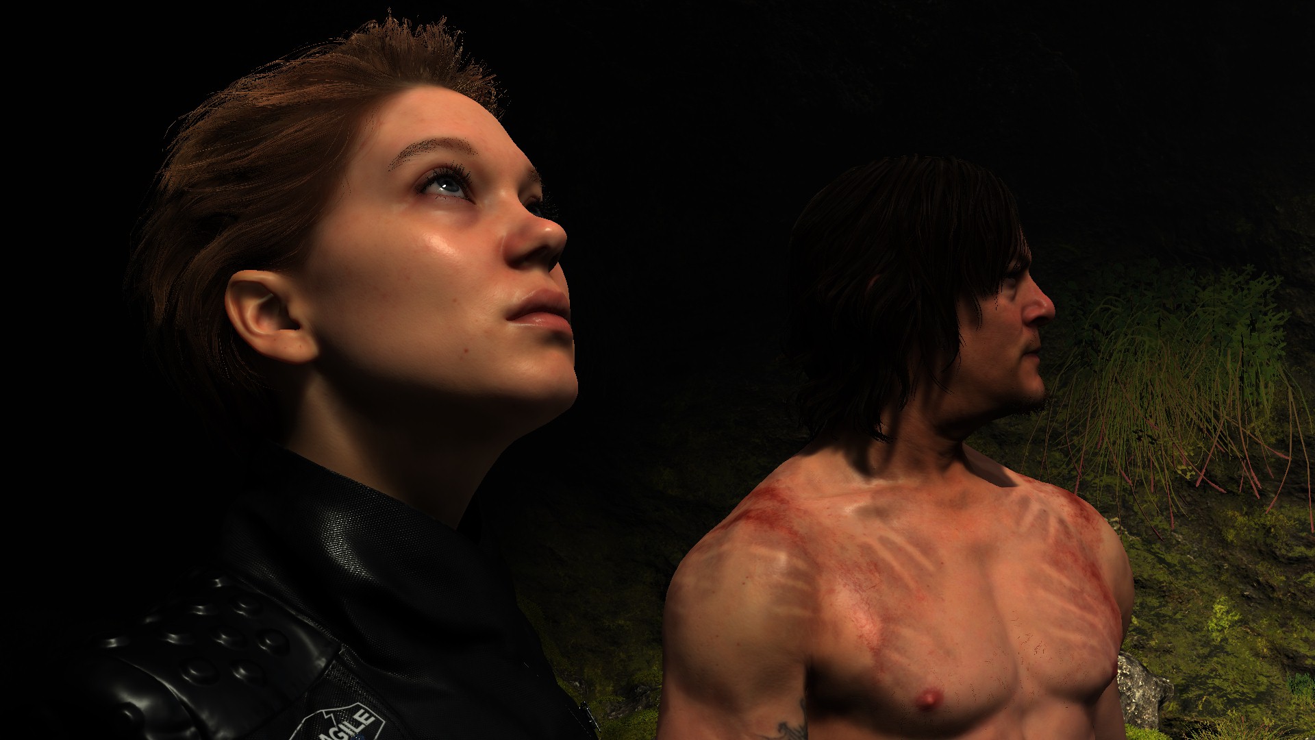
Aaaand YES! this is a very plastic moment of Norman Reedus!
And of course, for the sake of why not, here are some SSAO steps for multiple pretty frames!


Don’t get upset by the number of examples
Please don’t get upset by the many examples per case. You might’ve noticed by now that since the 1st article, that i put many examples per case most of the time, this is not because i’ve penalty of free time, or enjoy taking screenshots, but actually this is back to an old saying that me & many in the Middle East get raised with, it translated to English as “With examples, it becomes crystal clear” or in Arabic “بالأمثال يتضح المقال”
When studying complex subjects such as Chemistry, Physics & Math in high school, many teachers kept saying that same phrase again and again and again after explain each lesson and before diving into endless examples, and as a matter of fact, the teachers who did that, were my favorite ones, and were the ones i was learning smoothly from, and even after 25+ years from high school, i still remember most of the knowledge they explained, due to the variation of their examples (even thought i do nothing useful with chemistry nowadays). And growing up, i found this very helpful at career wise as well, since i started in this career, specially with pretty much everything i learned was self taught, i found that when getting the “case” in question covered with more examples, even if i have to make up my examples when a book or article doesn’t have enough, because i’ve got no teacher or nor professor to explain, that makes it digested smoothly in my mind, even if there were ZERO text explaining them!
So, it really is بالأمثال يتضح المقال !
Copy & Clear
Yet another ClearRenderTargetView()
Shadow Caster Height Field (Sun Shadowmap Long Distance) [Compute]
OutTarget / 3DTexture
HeightTerrain, HeightObject, ExtraHeightObject, ShadowCasterHF
Copy & Clear
Yet another ClearRenderTargetView()
Indirect Forward Pass (Light Sampling)
Get out a LightSamplingPositionTexture, LightSamplingNormalTexture, MiniatureLightTexture, and depth one
//TODO (Examples)
Copy & Clear
Yet another ClearRenderTargetView()
Shadow Pass[es]
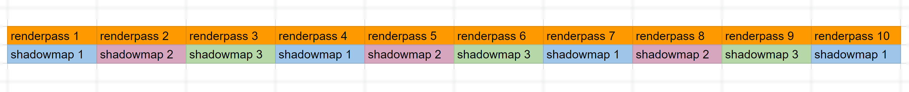
An average of 10 depth only shadow pass for direct light sources (can go up to 15 in cinematics). All the passes are co-ordinating on a handful few of square power of two rendertargets/shadowmaps which are most of the time are either 1024*1024 or 2048*2048 of the foramt R32_TYPELESS.


because it seem to be always the case, and it makes perfect sense!
There is nothing out of the ordinary here, and the only thing that is worth mentioning is the distribution of the passes workload. As you see there is a ton of landscape to cover, and this is why things are split into 3 or more shadowmaps but not in 3 passes, in 10 or more, and this is done by going back and forth between the shadowmpas in each pass one by one, and it is quire rare to have a shadowmap that is fully completed in a single renderpass. So the final result is something similar to that following diagram
Now, go to cinematic, which is quite different story, in cinematics. Cinematics in DS is 3 types, the 1st one is prerendered videos, the second ones are like gameplay moments with gameplay quality boosted, and this is not very different from the gameplay (in fact the Fragile frame above is one of this category), and the last type is the cinematic that is high quality and not prerendered, and for this type shadowmaps usually different.
It still use the same idea of rendering shadowmaps one after another back and forth, BUT the twist here is that there will be a single final shadowmap that contains everything together (less res of all combined) by the end. So if in a one renderpass there is a shadowmap that is completed, it get scaled down then composited to the final big shadowmap (that is most likely not square anymore) before proceeding in completing any of the other shadowmaps.
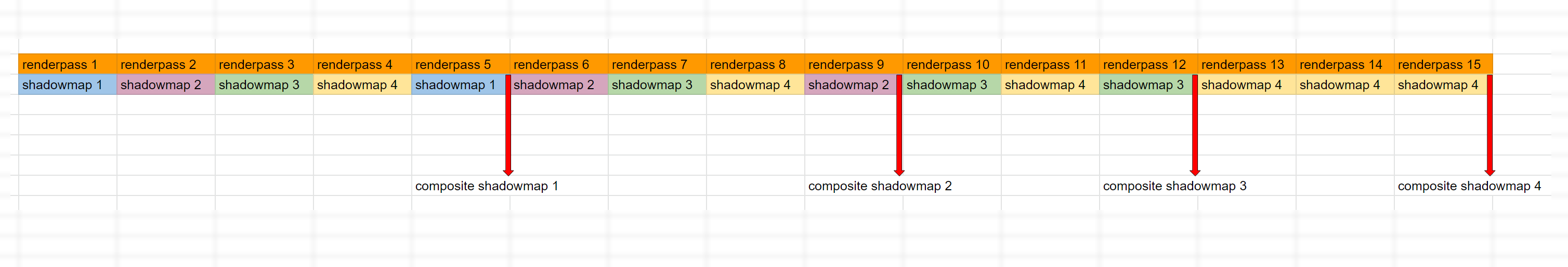
So basically the one shadowmap that is ready, it get composited, and not written to it in any future renderpass anymore. And to translate that to real example (with more shadowmaps than the diagram of course), take the frame below
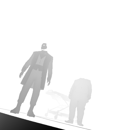
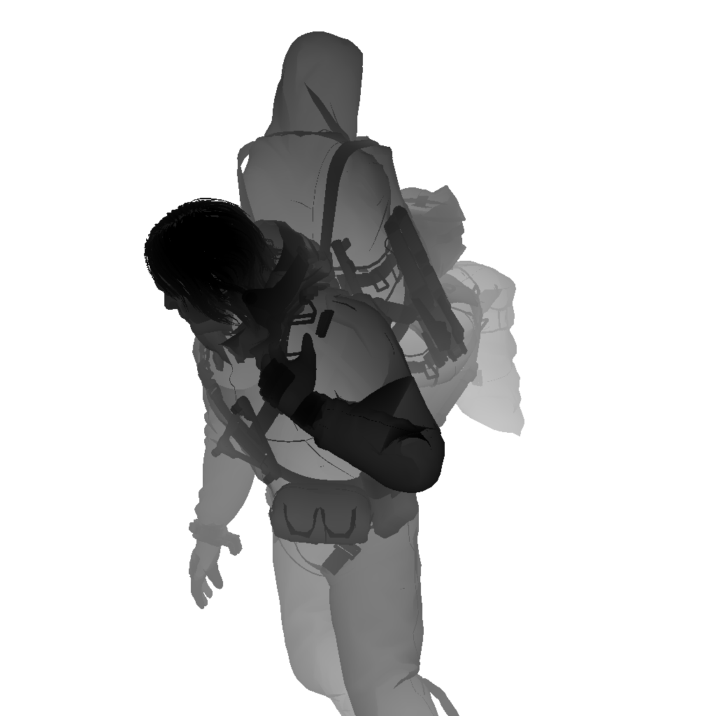


And from another cinematic frame (perhaps less shadowmaps as well)


Prepare Volumetric Light
Now while everything looks tidy so far, but the Volumetric lighting to texture step, is not actually “very” independent, and it is not taking place after the Shadow Passes. Most of the time, in between the different shadow passes, the renderer take a break from working on shadows, and do process the fragment shader responsible for Volumetric Lights calculation. So is this something made in purpose, or failure in some Multithreaded rendering hopes,…only the team behind the game can tell.
//TODO (Examples)
Local Light Sources
Yet another step that might overlap with the shadow passes (most of the time) and not necessarily wait until all shadow passes ends. At this step basically the deferred light get calculated for the local light sources such as point & spot lights using the GBuffer rendertargets. This step is always present regardless it’s a cinematic or gameplay, the length of the step depends on the local light sources count.
//TODO (Examples)
Cloud Rendering [Compute]
A compute pass of few dispatches to get out a CloudTexture (similar to the ones carried over from the previous frame)…Cloud coverage.
Direct Light & Sun Shadows
Apply the sun/moon light (single directional light src), as well as the shadow maps that were generated earlier
interestingly have an output rendertarget that looks interesting and never used for the rest of the frame life!
//TODO (Examples)
Volumetric Light [Compute]
Outputs an IntegratedVolumeLight with the possibility of format change from R11G11B10_FLOAT to R16G16B16A16_FLOAT
The depth of the volume is basically the slices. Can see examples below where it is used.
Another funny observation, was the use of 3d noise texture so it can add some “movement” to the volume, which is common, but what was not common to find that the 3d texture tagged as KJPFogNoiseTexture, and many of the params passed to the shader are prefixed with KJP to stands for Kojima Productions ^_^ not sure if that type of things are self-pride, or because those parts will be possibly shared back with Guerrilla, so it becomes easier to distinguish parts that came from Japan team!
Fun Fact
While writing that part, it came to my attention, that the frame order of execution, almost never changed since the days of Kill Zone!

Prepare volume light, Deferred, multiple shadow passes, sun/moon light, volmetrics…
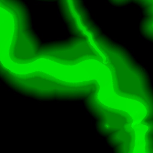
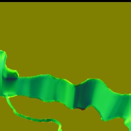
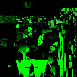
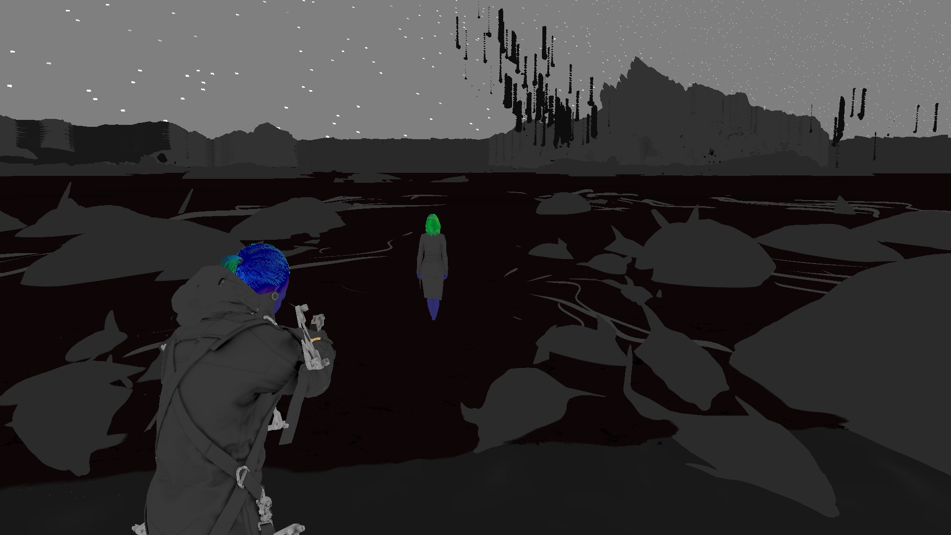
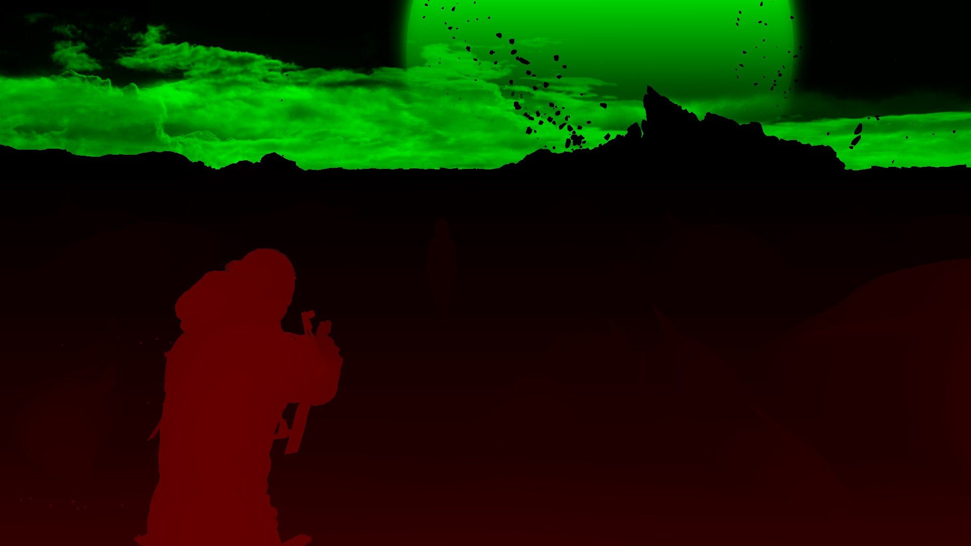
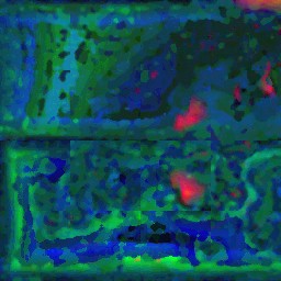
Volumetric Clouds
prepare in few draws a cloud buffer (the green one)
//TODO (Examples)
Volumetric Clouds [Compute]
most likely raymarching
//TODO (Examples)
Water [Not Always]
Only where there is water meshes in the frame
//TODO (Examples)
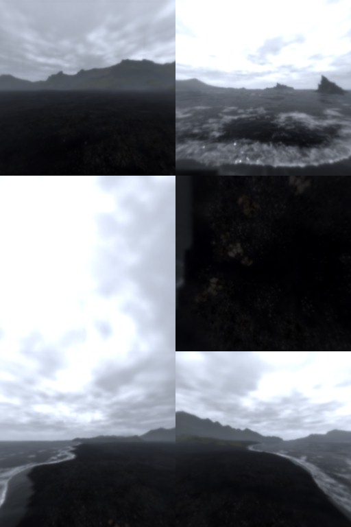
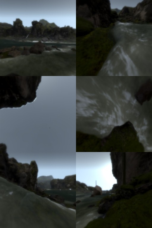
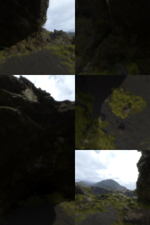
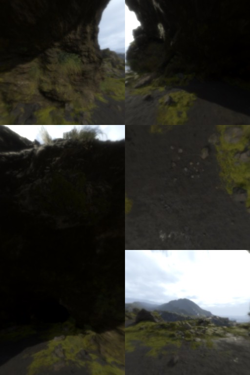
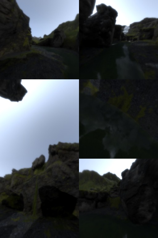
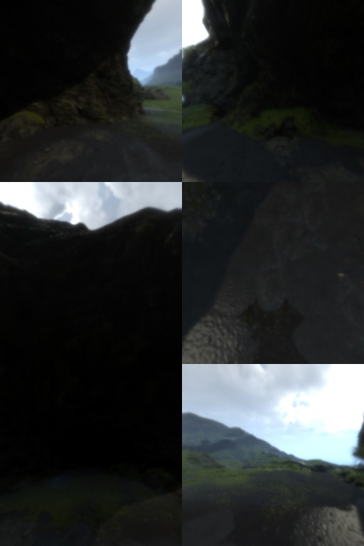
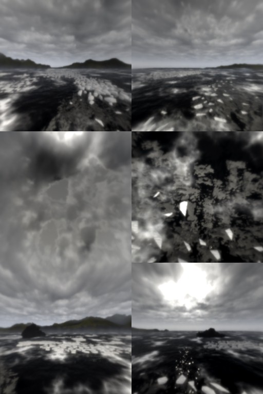
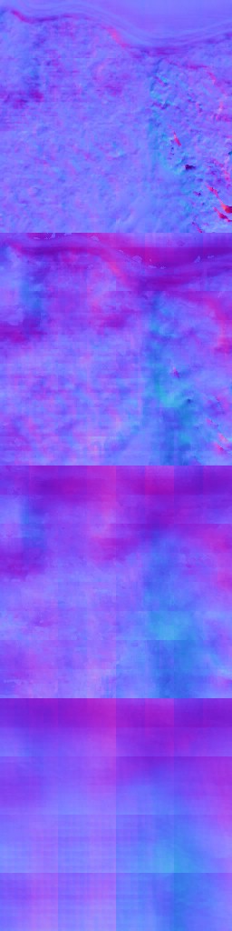
Prepare Cubemap 3D Texture [Compute]
Needless effort to recreate a new 3d cubemap texture from existing one, but only generated less mips (7 instead of 9), but at the same time change format from BC6_UFLOAT to R16G16B16A16_FLOAT… Why not baked before shipping the game?
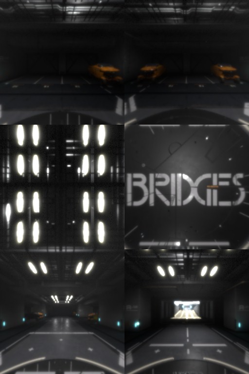
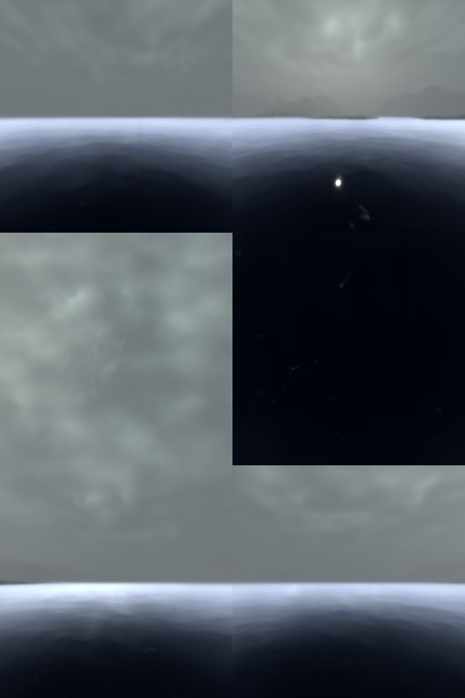
Examples of the cubemap are seen below.
Reflection Texture
This is going to be a step that is broken down to multiple steps, in order to prepare the needed render targets one by one
1.Reflection Mask
With the MotionRoughtnessTexture, ReflectanceTexture as well as LinearDepthTexturePyramidMin, the fragment shader end up with a 960*540 R16_TYPELESS mask texture that is used later (in the next step) in a compute shader to generate the ColorBuffer as well as GlossBuffer of the frame.


2.Color & Gloss Buffers [Compute]
using the LinearDepthTexturePyramidMin, NormalTexture, PrevSceneTexture, MotionRoughnessTexture as well as the generated MaskTexture from the previous step, a single compute dispatch runs to generate the OutputColorBuffer as well as OutputGlossBuffer.


3.Color Buffer to Quarter Texture Mip Chain
Taking that previously generated in the compute dispatch OutputColorBuffer, and in multiple executions of the blurring shader, it get downscaled and blurred at few steps.
i.Scale & Mip
Scale that Color Buffer that came out of the previous step from 960*540, to 480*270, so not it’s a “Quarter” of the target frame size. With that in mind, here as well down mips are generated and stored in that texture.

And of course, it’s a pyramid texture, and it contain just mips,…nothing fancy, but i’ll put below it’s chain details for the sake of demonstration, no more…


ii.Blurring Mips
As you see, by now that Quarter Texture Mip Chain is made of multiple mips (5 to be exact), so the shader run twice per mip, so it blur each mip horizontally, and then vertically….too much work!


Eventually, all that work, to end up with what so called the Quarter Texture Mip Chain (with all blurred and life is good!)

Totally Not Important Note (or may be important… idk)
I intended to put all those steps in detail, even though it was very boring to extract, this is not because i’ve a lot of time to waste & not because i do have a lot of online storage on my blog. But my main reason here is because i always like to take any opportunity that makes me “pause” and wonder…and if you look to this matrix of ~15 images, you need every time to see it to think about 15 different commands or invocations that are full of instructions that ran per each mip in order to:
1st generate that mip,
2nd blur it on X,
3rd and finally to blur it on Y…
A lot of work, that yet done in ultra seconds! coming from DOS & Win3.11, expensive RAM in megabytes, no actual graphics card & software rendering…those type of things (the images above) makes me always want to wait, wonder, think about where we came from, and where we are heading in terms of the power of computing. Regardless, those steps are needed or not, can be optimized or not, it’s just beautiful to witness…
4.Generate the Reflection Texture
Not sure what is going on. Taking the GlossTexture, HalfTextuer as well as the previously generated QuarterTextureMipChain, we end up with the Reflection Texture that is 1/2 of the target resolution.
5.Accumulate Reflection Texture
as everything else, in order to avoid some artifacts, why not just accumulate with the previous’ frame results. So using the MotionVectors, Previous frame Reflection Texture, the Reflection Texture that is just generated in the previous step as well as the Mask Texture, we end up with smooth and ready to be used final Reflection Texture of the current frame (soon to be called previous Reflection Texture of the previous frame. Life is short!).


Copy & Clear
Yet another ClearRenderTargetView()
Diffuse Light


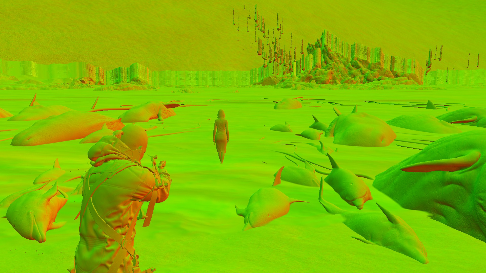
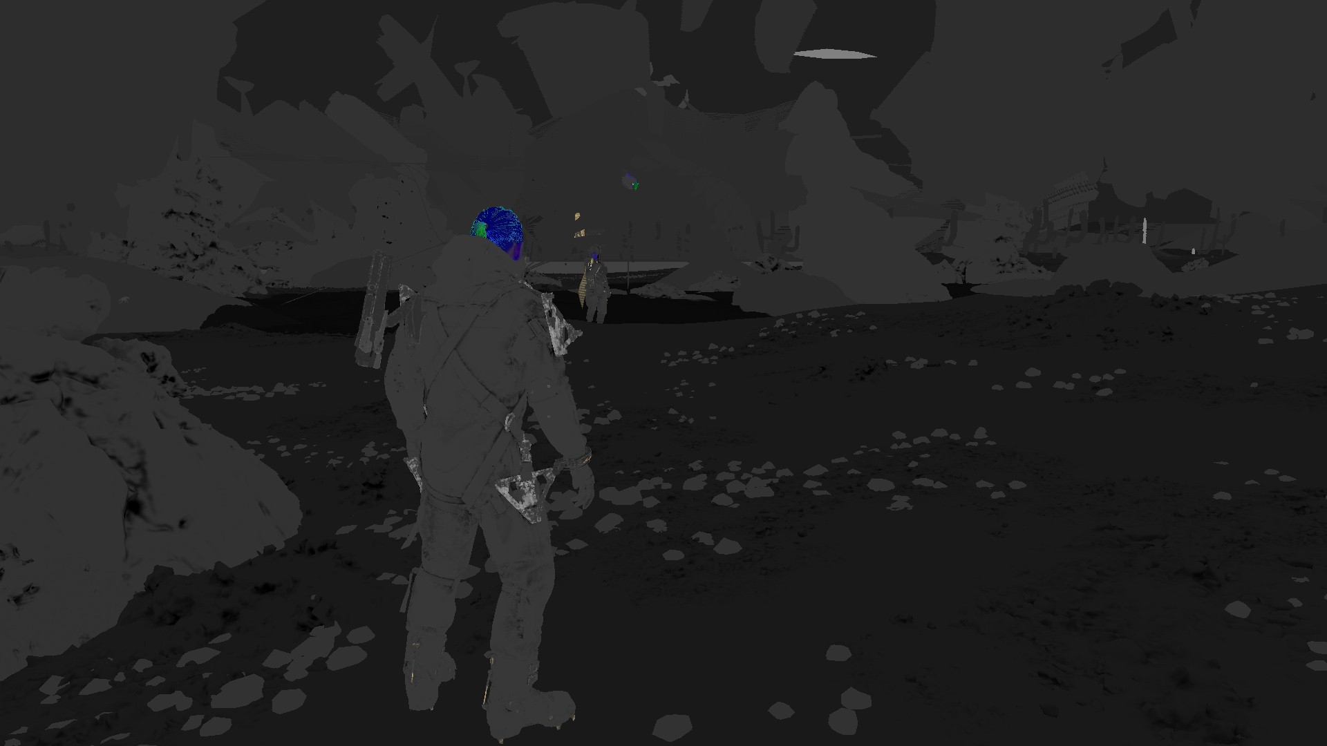
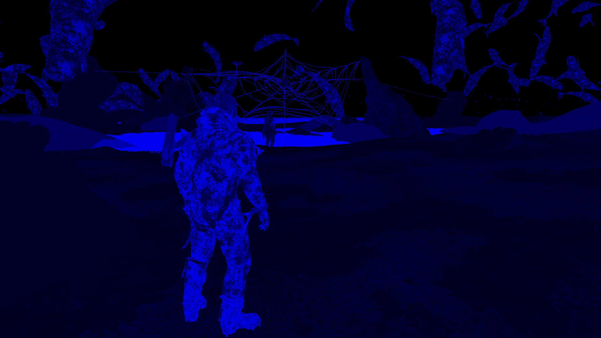
Now if you think that i might’ve uploaded images by mistake, or was falling asleep and attached more than enough images in that section…you defiantly are wrong! Everything you’re seeing above (even if it seem like “duplicated”) are exactly what passed to the shader in order to do the lighting. Apart from the last 3 images in the last row, everything is individual inputs that are passed to their own parameters. So what on earth are all those inputs, let’s break them down in case it is not clear:
1.Common Textures
Albedo, Normal, Reflectance, MotionRoughness, AmbientBRDF, Environment, AO, Reflection, Depth, Irradiance… All those are self explanatory by name. You either learned those at school, life taught you the hard way what are those, or mom told you about those textures when you were young, let’s skip those.
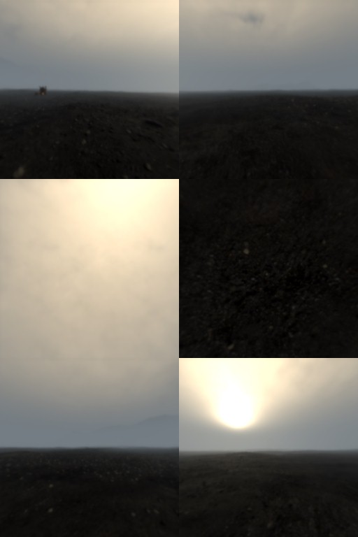
2.More Common Textures
The local environment cubemaps for local reflections…When you see all those, don’t just think it is a big waste of resources, or the same resource keep passed again & again, nope. Same resource can be used many times, but i think it could’ve been handled in multiple different ways. As you see in this frame example above, pretty much every cubemap passed is the exact same one for the local cubemap (10) which matching already the generalized environment cubemap. There are two (the first two) that are using different ones. IMO if you’re going to use a single cubemap to fill 12 or 10 shader inputs, why not just have single cubemap passed, alongside a float param defining how many bound params are actually holding value for that invocation of the shader? It’s not the only way that i’ve seen before, but at least it is much more reliable, clean and perhaps much less resource intensive. Anyway, all in all, if you check more examples below, you would notice that the rule is:
– There is 12 local cubemaps
– There is 1 general cubemap
– When the local cubemap is not valid, switch to use the general cubemap one.
Also keep in mind, at most cases, the cubemaps here, are the one that came out of the compute earlier in the frame lifetime.
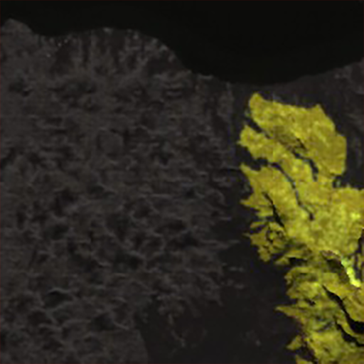
3.Kinda Werid Textures (IV Textures Set)
Important Note
NOTE: take this following description of the IV textures with a grain of salt! It’s all based on self studies & previous readings, but personally didn’t use that technique in a production before.
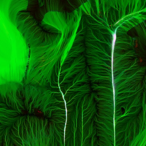
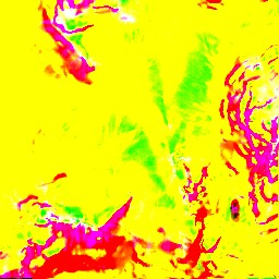
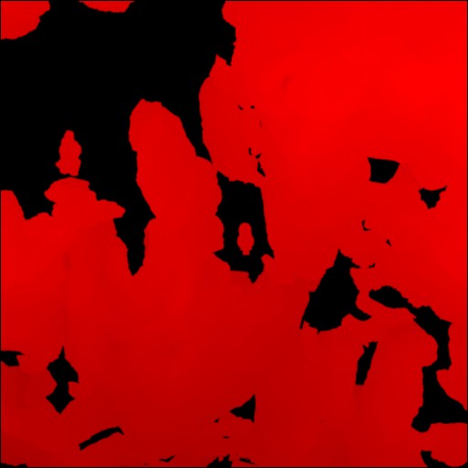
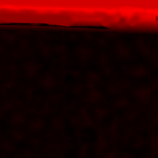
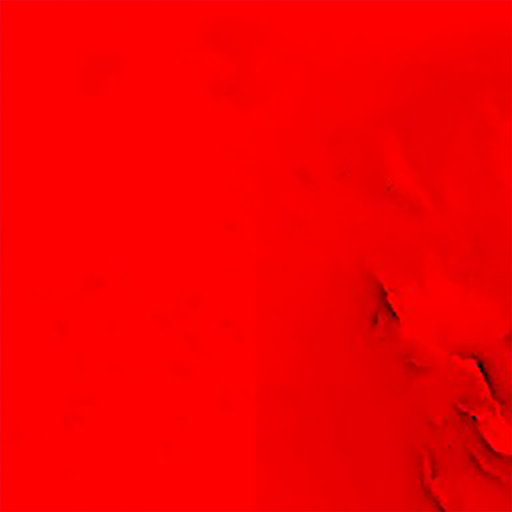
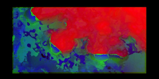
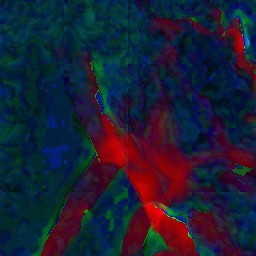
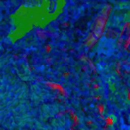
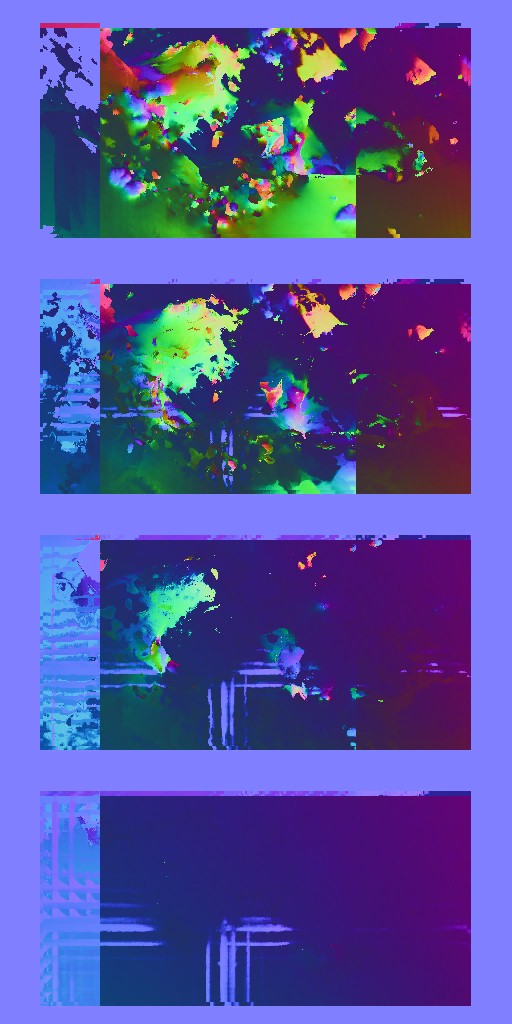
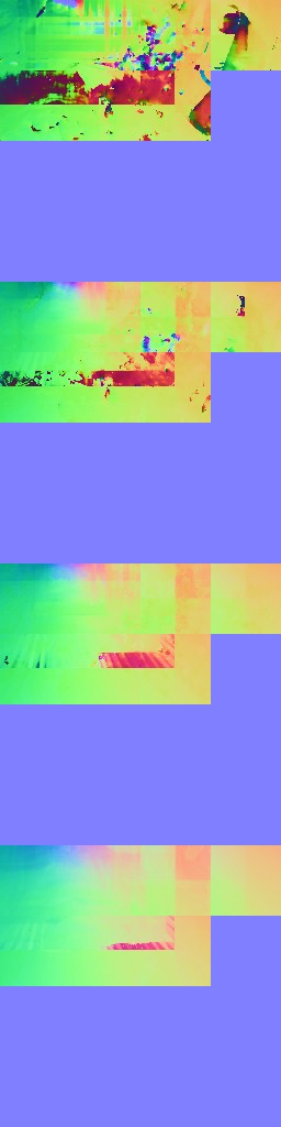
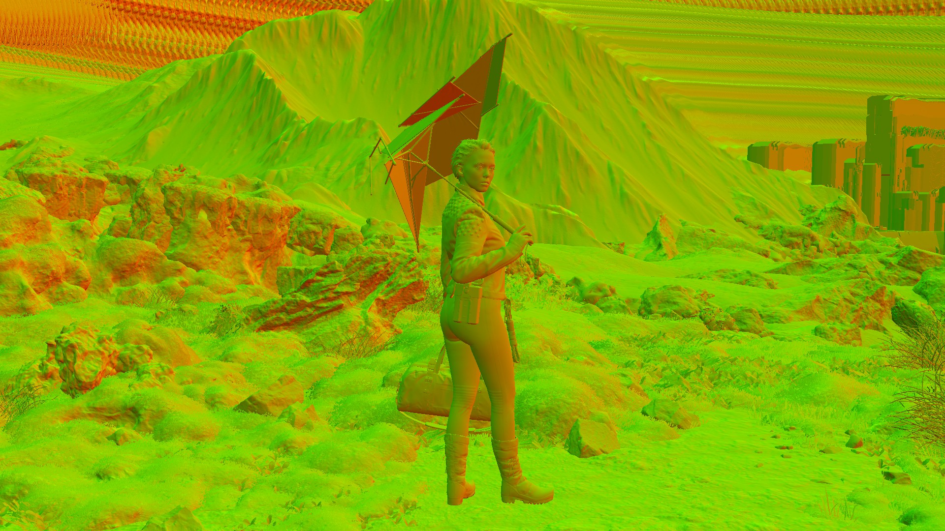
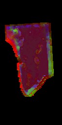
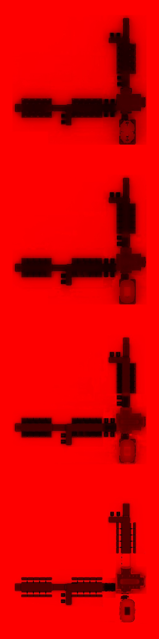
Those are the most rare to see textures in any other game (at least by their name & job, not their look), you would’ve noticed that there is a whole lot of textures that are all prefixed with something like “IV” to stand for “Irradiance Values” or “Irradiance Volume” or “Irradiance Volume Values”…anyways it’s irradiance & values related thing! Those textures are such as (Terrain, Height, SkyVis, Aleph, Axis) are for the environment, and they are working as follow:
-
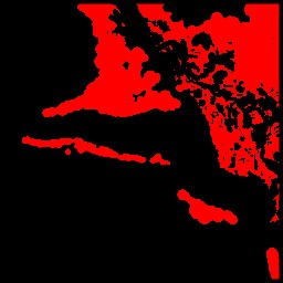
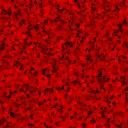
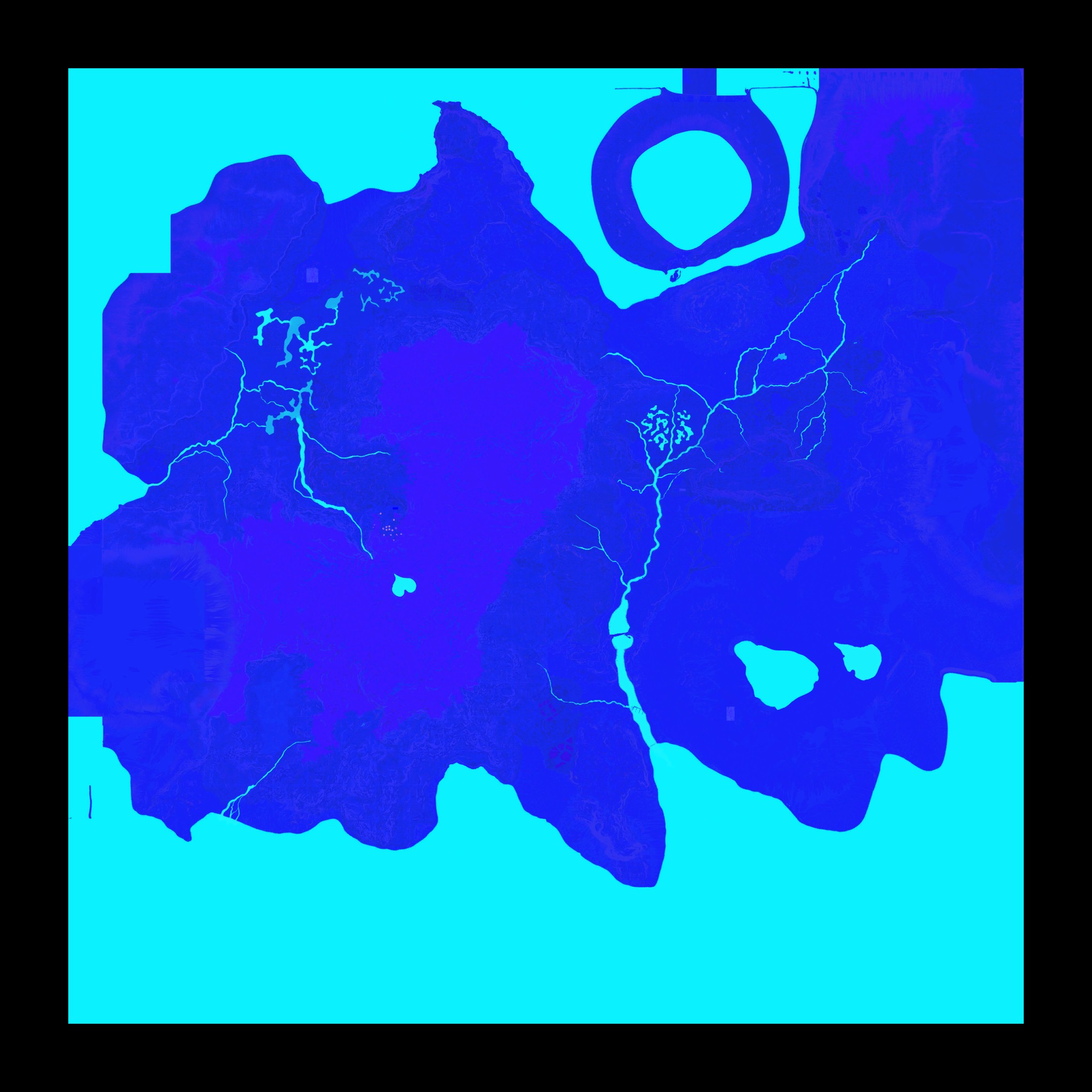
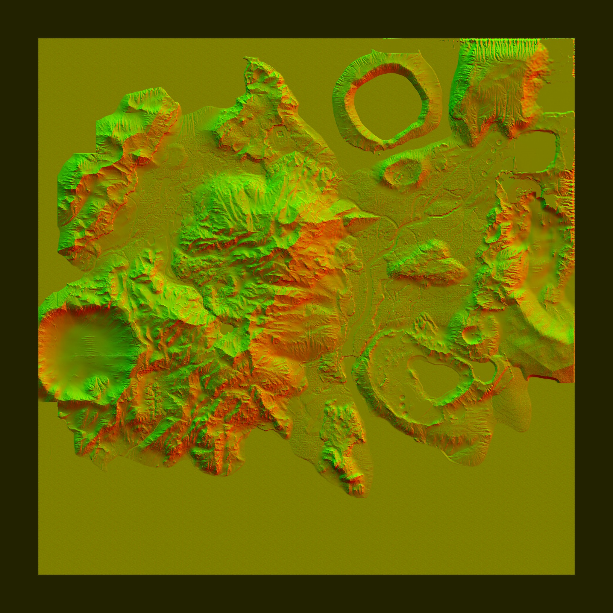
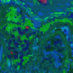
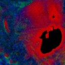
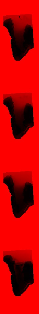
Terrain
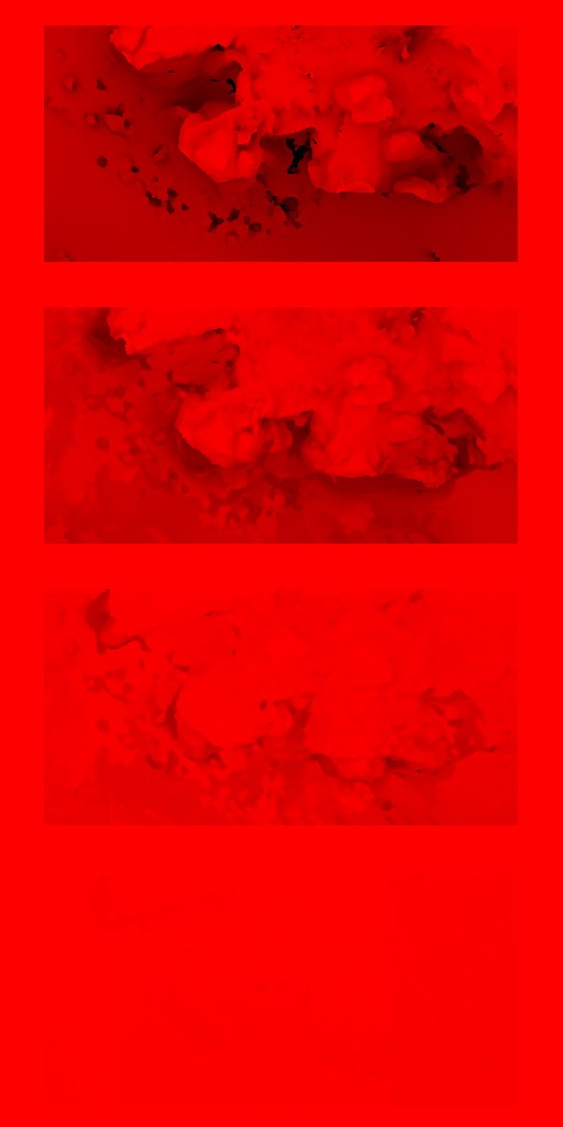
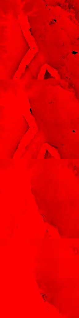
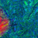
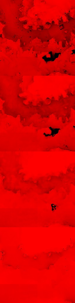
Is a top view of what is terrain and what is not. Basically terrain coverage for 4*4 blocks of the landscape. It is very common to see in a frame captured in the open world (exterior) in the middle of the mountains, that pretty much all terrain textures are very red. -
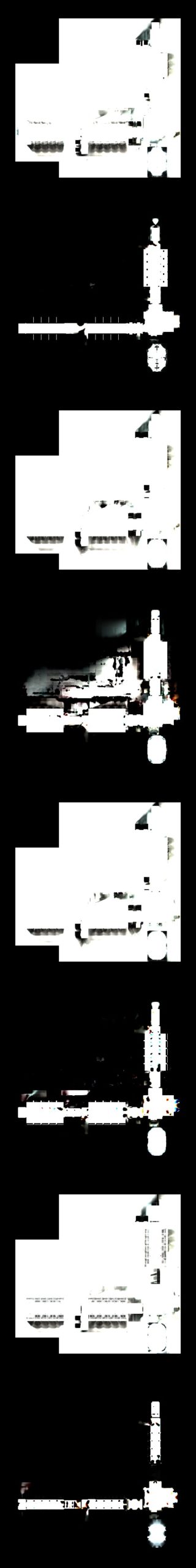
Height
Is basically the height of the ground in that 4*4 blocks of the landscape. -
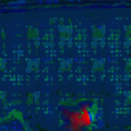
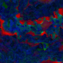
Aleph
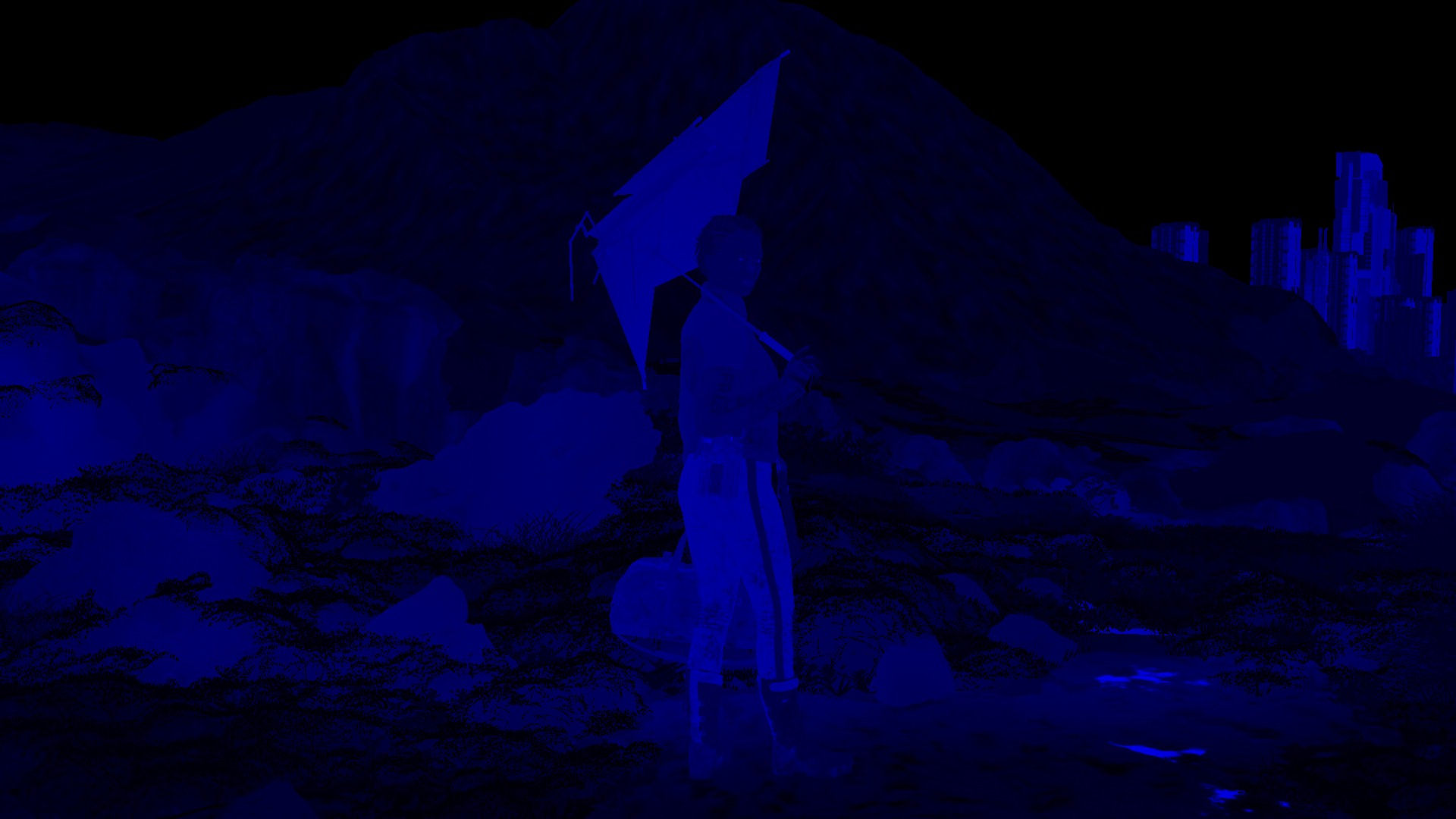
This is the most interesting one here. This texture is basically a spatiotemporal error tolerance map that is used as a guide to optimize rendering. The name it self might sound weird at first, the original name for that map was “Application Adapted Attention Modulated Spatiotemporal Sensitivity Map” and hence the “Aleph” came as short fancy name for it. The word “Aleph” itself is actually not a real word, it is the “pronunciation” of the Arabic letter “أ” or the Hebrew letter “ℵ” which is pronounced “Aleph, Alef, or Alif”, and it is not coincidence that both letters are the 1st letter in both Arabic & Hebrew alphabet. You can think about “Aleph” as an “A” in English, or “Alpha” from the Greek alphabet.
It’s been said that the Aleph map is used as acceleration technique, and in the world of realtime rendering it can be used at many & different forms, the most common ones are as a perceptual oracle to guide the global illumination algorithms, reducing lighting calculation times by an order of magnitude. In general used as a perceptual oracle to specify in advance the amount of computation to apply to a lighting problem (a….not specific). The most interesting use case that caught my attention in the paper (which is what i believe our case here) is to be used as part of the irradiance caching algorithm to modulate the ambient accuracy term on a per pixel basis, so wherever the Aleph Map allows for greater error for that pixel, a larger set of irradiance values are considered for interpolation, making efficient use of the irradiance cache. In another way, the Aleph map here, used to adjust the search radius accuracy of the interpolation of irradiance cache values.
For further information about the very deep technical details about the Aleph & how to generate them, check the references section, to be exact Yee et al. [2001]. There is an entire chapter in there discussing the application of Aleph map with the Irradiance Caching with some interesting examples where the Aleph map accelerated irradiance cache performed between 7 and 11 times faster!
Aleph = أ = ℵ
-
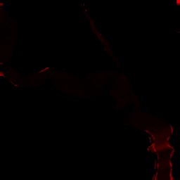
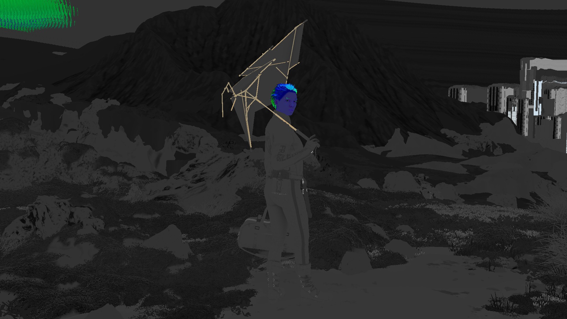
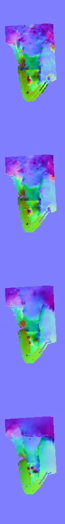
SkyVis
As the name might imply, it is the visibility of the terrain from the sky. The higher the terrain or mountains, the darker you will see the pixels. So very red pixels means more near to the sea level. You might ask, so why using skyVis & Height texture at the same time. Each has it’s own use case i believe, where the SkyVis texture captures the height of the “mountains” or the “peaks” we’ve in that 4*4 area of the landscape, the Height texture is more about the “details” of the entire terrain regardless far that point of landscape from the sea level, and regardless it is a Mountain or Valley. -
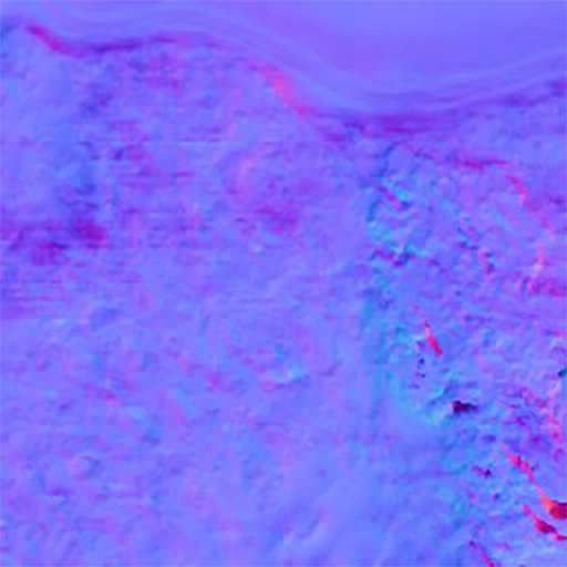
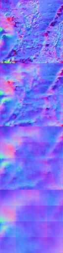
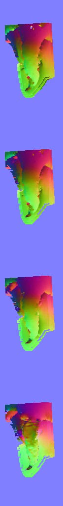
Axis
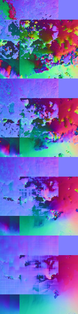
Where it looks like normal maps, but the Axis works with the Aleph texture, and i do believe it is working as “Saliency Map” which is used for velocity compensation with a (what-so-called) Hi-res Aleph map not standard Aleph map….Kinda..

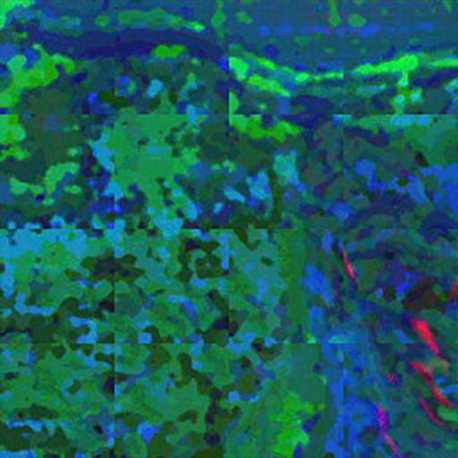

and below is animated bled between all of them for more clarity
IV Textures Set Genral Notes
-
Those textures above are for a single slice from the texture set. Each slice is (as you might notice the seams) a 4*4 blocks of the terrain (each terrain block is a 256*256 of the game unit, which i believe is meter). So a 256*2048 Texture in that set is made of 8 slices where each slice is a 256*256 pixels, each slice is a representation of a 16 blocks of 256*256 meter.
-
The Terrain texture, i flipped here for the sake of demonstration, and to show you how it relates to the rest of the texture set. But it is always flipped upside-down when passed to the shader, and not sure why!
-
Mostly the texture set contains 1 Aleph + 1 Axis texture. But there are cases where you will find there is a 2 Aleph + 2 Axis, this is basically happens in the maps with larger terrains (exterior in a very open landscape, example 5 below is a good candidate).
-
All those textures are generated at compile time. There is none of them that being generated neither with a fragment shader nor with a compute shader. All are either generated by artists while working in the level editor/world designer, or auto generated when terrain imported into the engine, or even at cooking time for the game package…can’t tell, but defiantly not at runtime.
-
Last thing, is that the Aleph textures i put here in all the examples, is boosted to the “sweet spot”. But in fact, the Aleph texture the way it is in the capture is very very dark, but i do boost it a bit. With that said, you might think it is made of 4 rows that has 4 black rows in between them. But this is due to the boosted values. Those black rows, are actually holding values, and below i put an “approximation” of how the Aleph texture should look like in a normal color space (just if it is a usual PNG)!


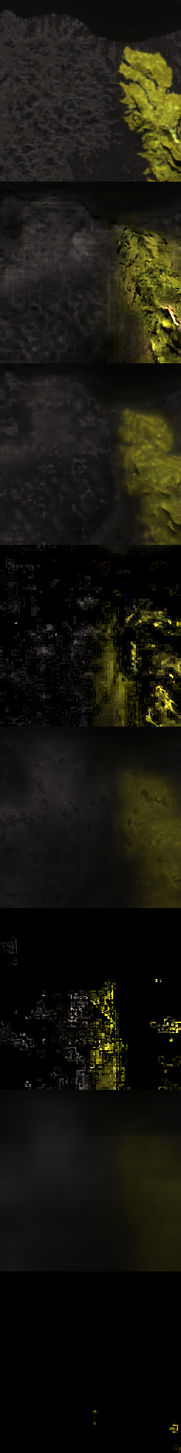
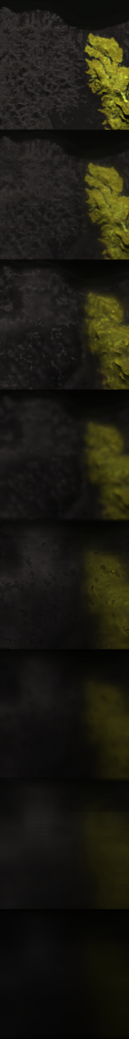
sadly the website thumbnailing feature looks bad, and showing in full size
will be bad idea, i didn’t want you to keep scrolling forever! : )
So, all in all. That concept of IV Textures Set and the utilization of the Aleph textures thing, is something Kojima’s Decima only or general Decima feature, only days can tell. Hopefully one day it will be possible to dig the next Kojima game or the Forbidden West on PC. That feature remains yet vague, magical and interesting enough to remember it in the future.
Things that i did not personally like, is the fact of using individual textures instead of texture arrays or 3d textures. It could’ve resulted in much more clear renderpass, easier to debug frames and eventually more readable and clear code at the programmer’s end. The fact of using a whole lot of IVTerrain, IVHeigh, IVAleph, IVAxis, was not that interesting to me, specially each of those is made of a group of slices that are 256*256 or 512*512 which could be managed better in 3d textures/arrays.
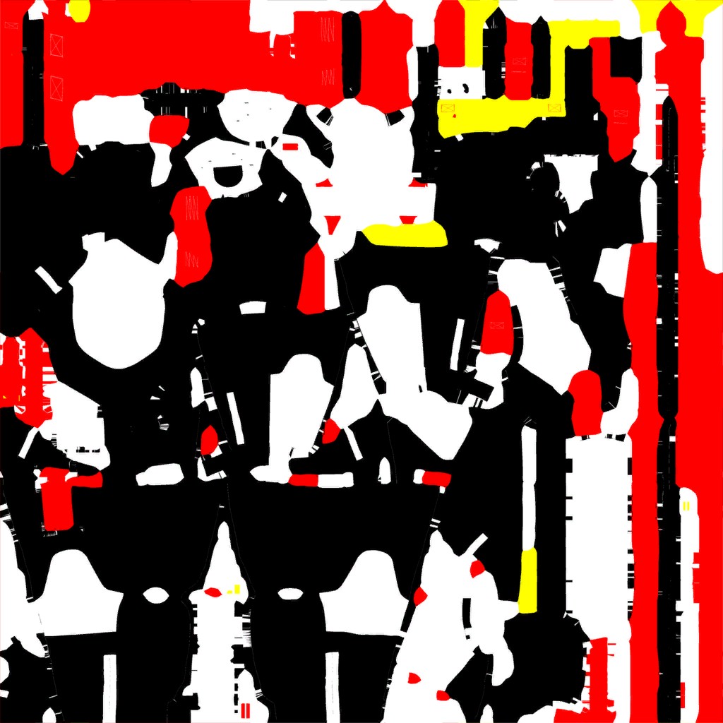
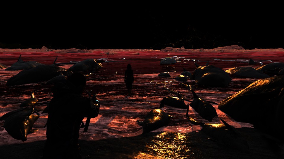
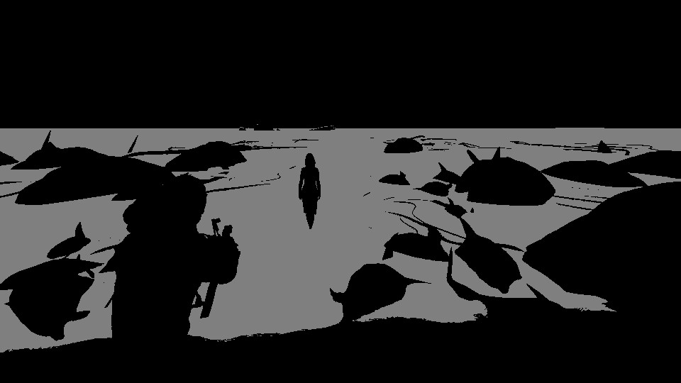
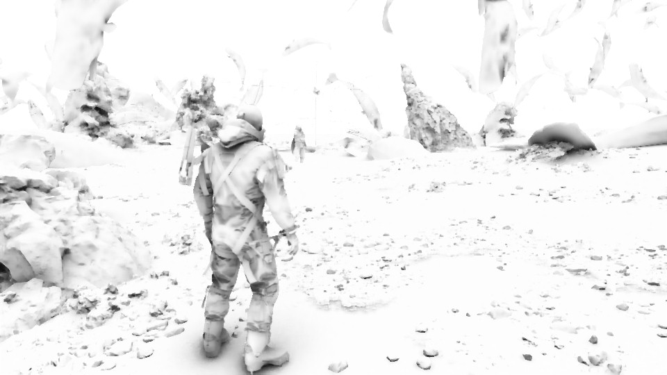
4.Outputs
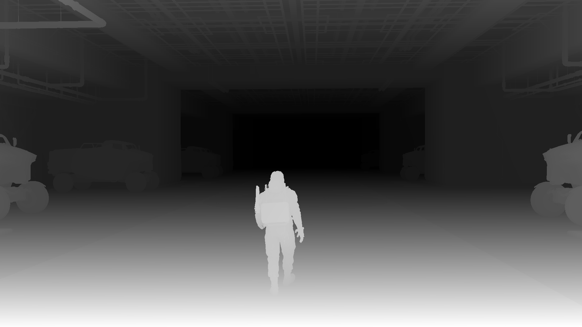
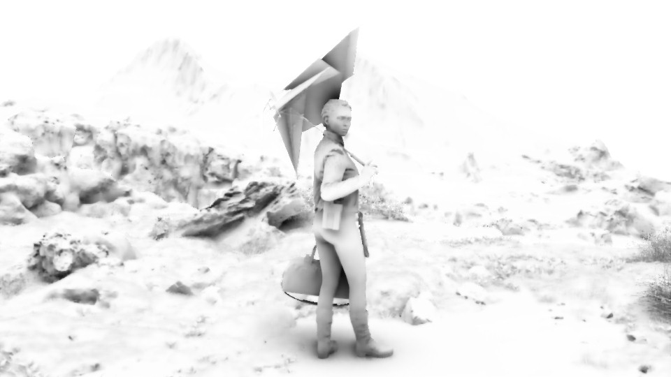
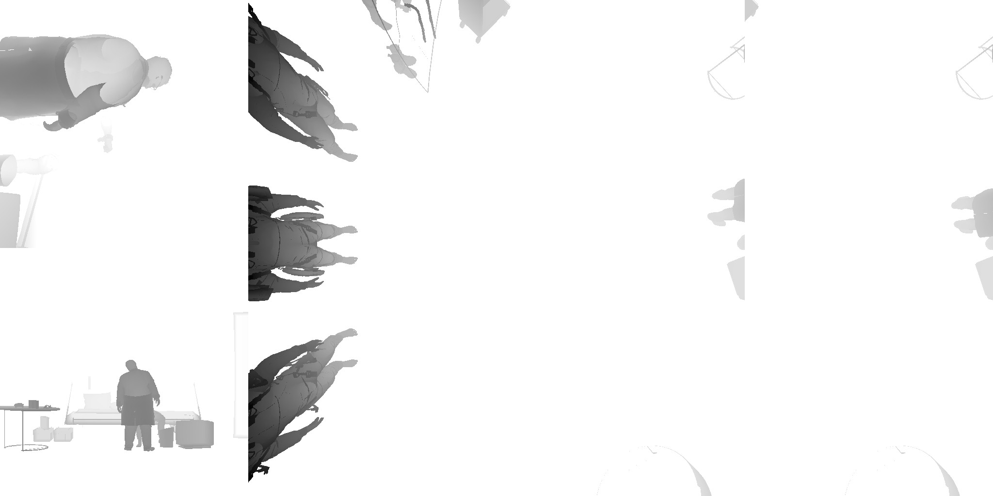
Regarding the outputs, there is the Diffuse frame, of course by the end it doesn’t look like the image above, i wanted to show the impact of the direct & skybox lights, but in fact it looks a little bit different after applying the reflections
At the other hand, the second rendertarget in the outputs list, it is an interesting one that is in red & green. It is a full depth in a different format stored in R, as well as the Blend buffer that will be used later and stored in the G for now. This blend buffer is used with sky elements but we will come to this later. It is not so long until as in the next drawcall the depth get isolated alone in that same rendertarget, leaving the G channel fully black.

Because i like to always investigate multiple captures in parallel, and because with multiple examples things gets more clear and more interesting, and it’s my habit to put few examples for every phase. But because this phase have many resources, i decided to put the examples inside those collapsible tabs below. Feel free to investigate further examples if you would love to, otherwise, glad that i (for the first time in those articles) did not occupy your screen with something extra!
Example 2 – Cinematic


No, i did not forget the Reflection Texture….But it’s not useful at this frame, here it is (the little 4*4 below), and yet, it’s one great performance decision.

Diffuse vs Diffuse with Reflections vs final swapchain

And finally the FullDepth with and without the Blend Buffer

Example 3 – Gameplay


Diffuse vs Diffuse with Reflections vs final swapchain

And finally the FullDepth with and without the Blend Buffer

Example 4 – Cinematic


Diffuse vs Diffuse with Reflections vs final swapchain


And finally the FullDepth with and without the Blend Buffer
Example 5 – Gameplay


Diffuse vs Diffuse with Reflections vs final swapchain

And finally the FullDepth with and without the Blend Buffer
Example 6 – Cinematic


Diffuse vs Diffuse with Reflections vs final swapchain
And finally the FullDepth with and without the Blend Buffer

Few interesting observations, first if you had a look at all the examples, that the IV textures are not always the same count, sometimes it’s 4 other times 5 and even 1 at many cases! But in general, the set count (IVHeight, IVTerrain, IVSky,…etc.) will always match each other.
Also reflection is not always there, for example in multiple examples (cinematics always), you would find a 4*4 black Reflection Texture.
And finally the local cubemaps are always passed as 12, which seems to be fixed number and the cap limit for Decima.
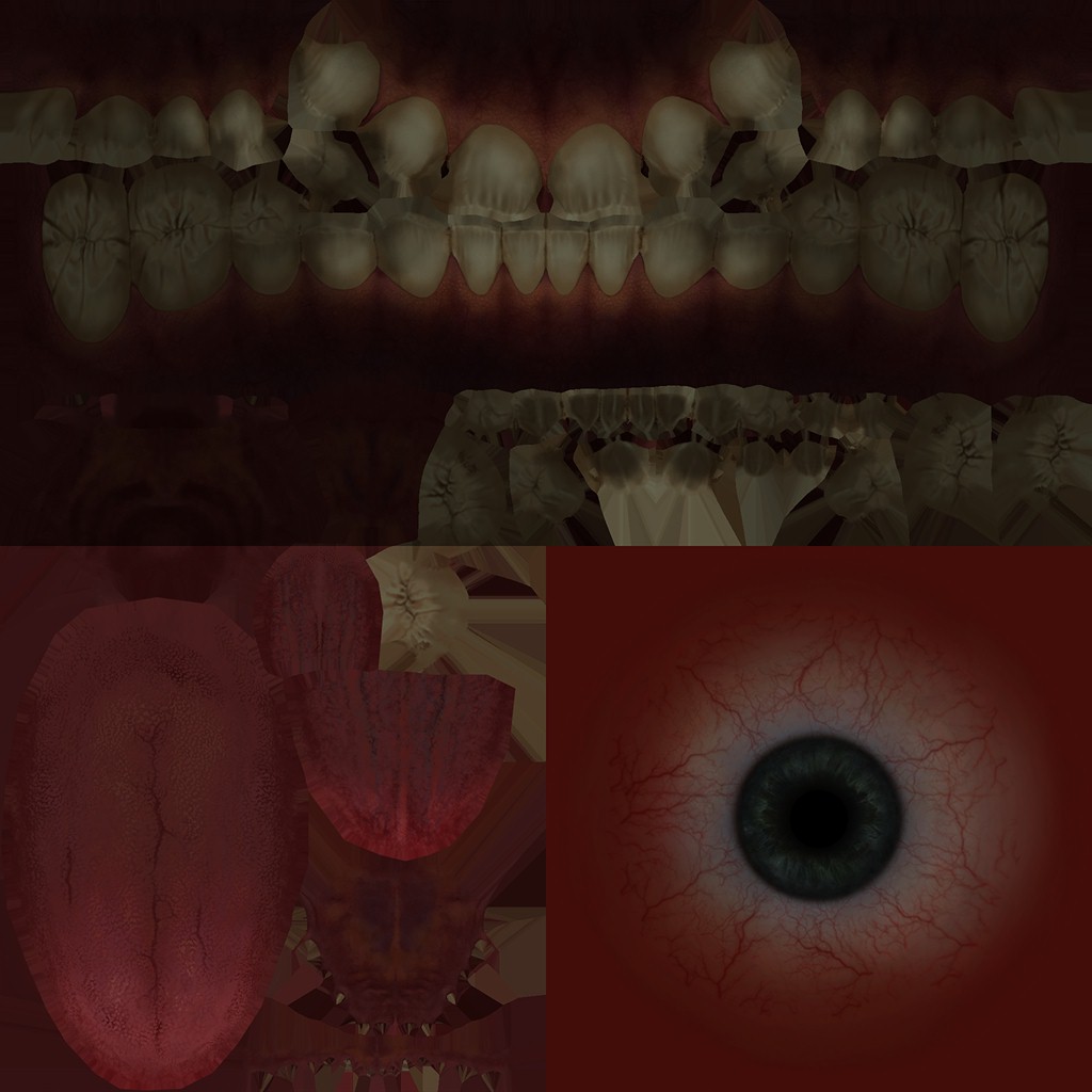
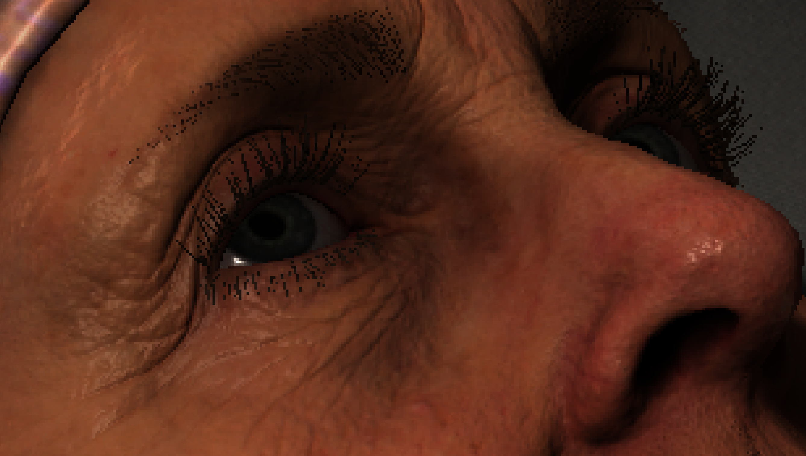
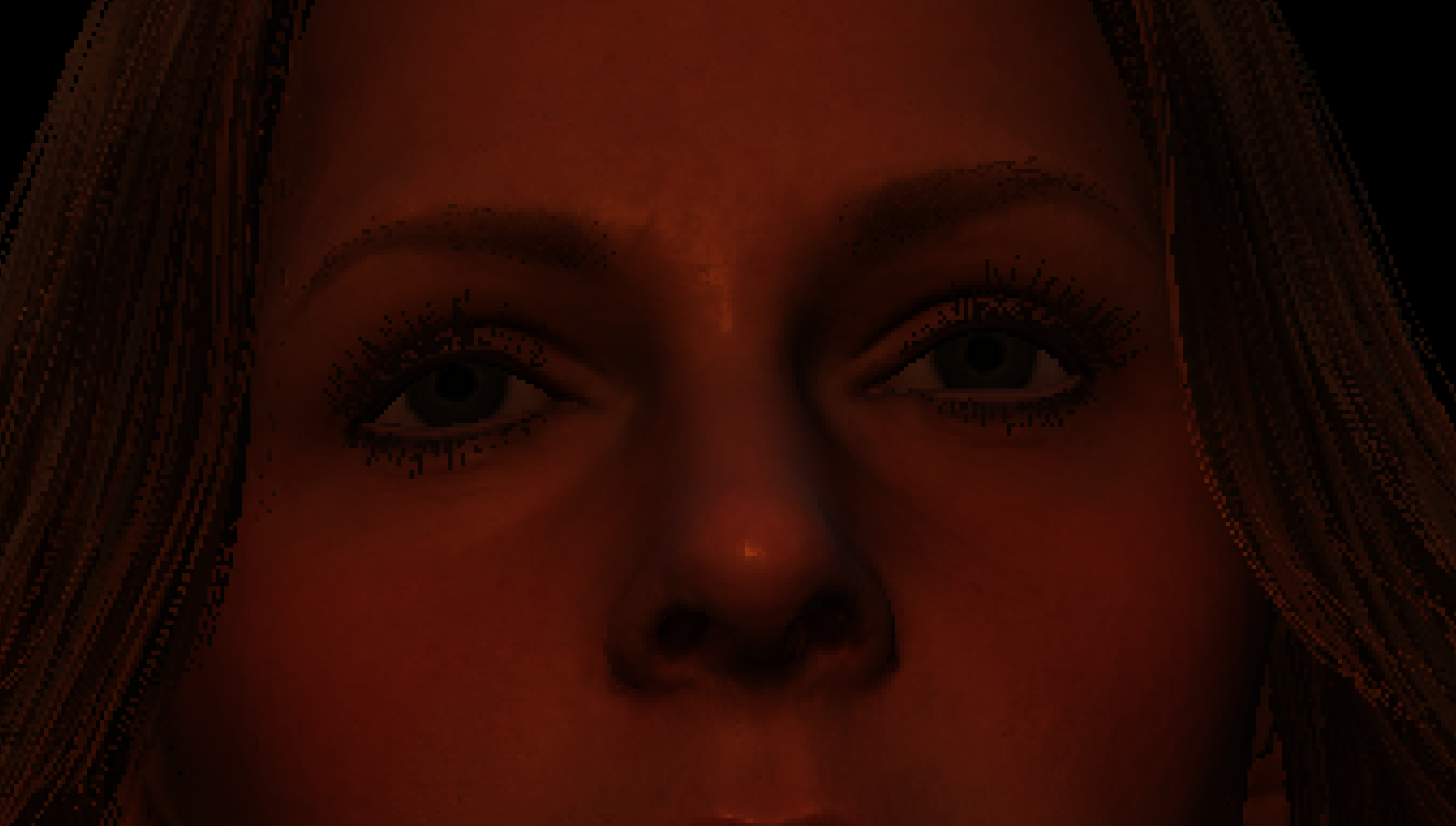
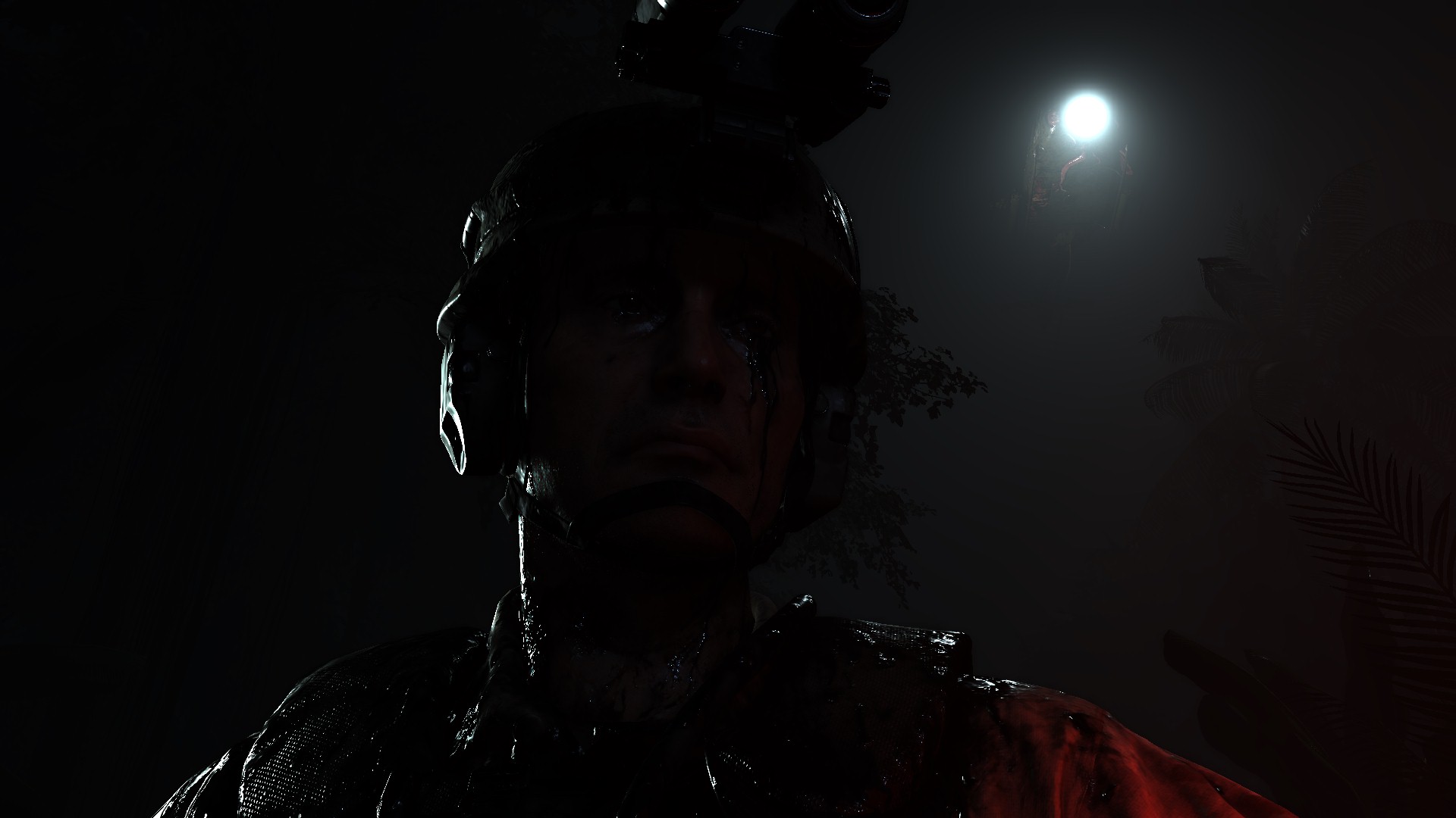
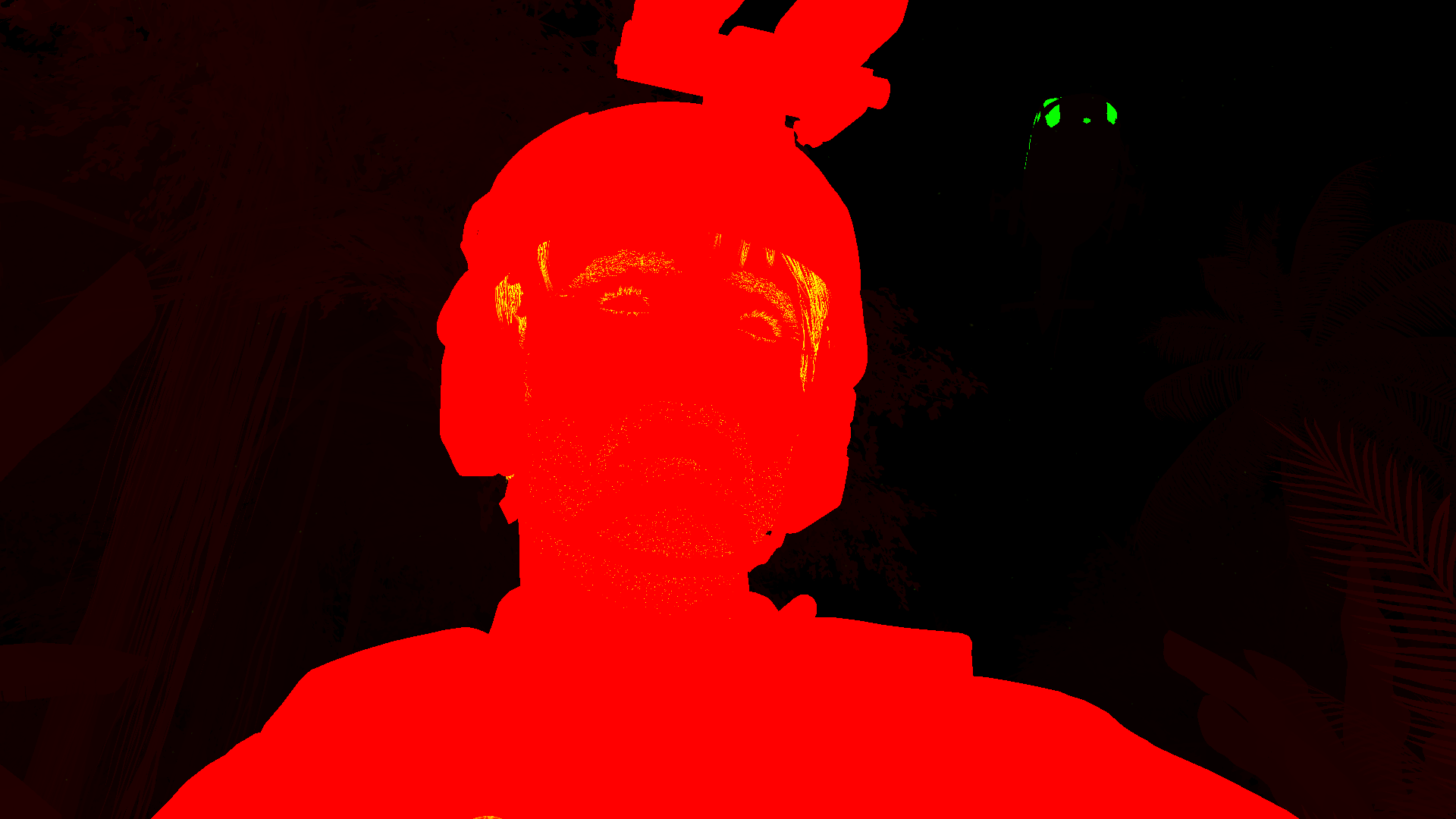
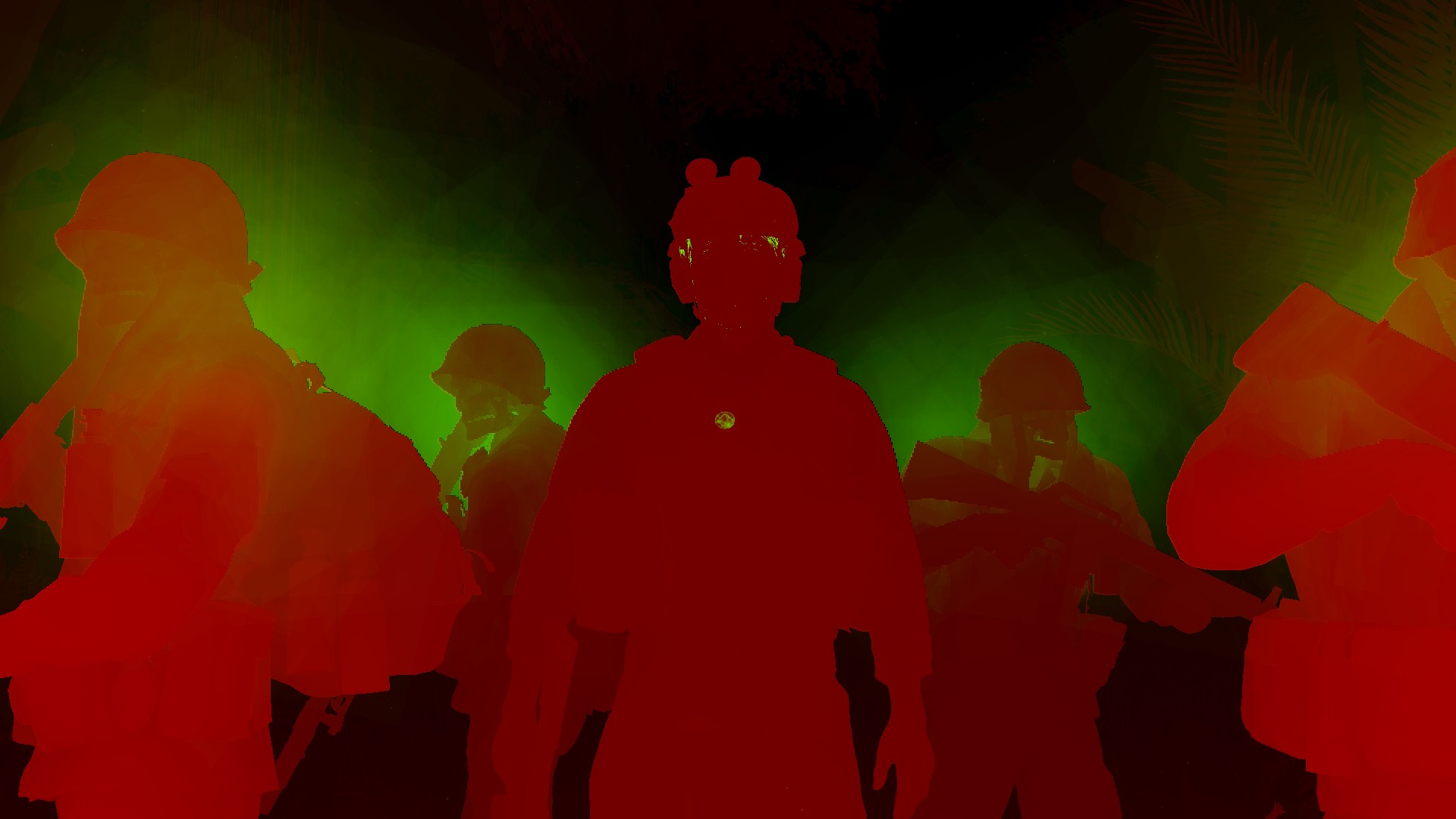
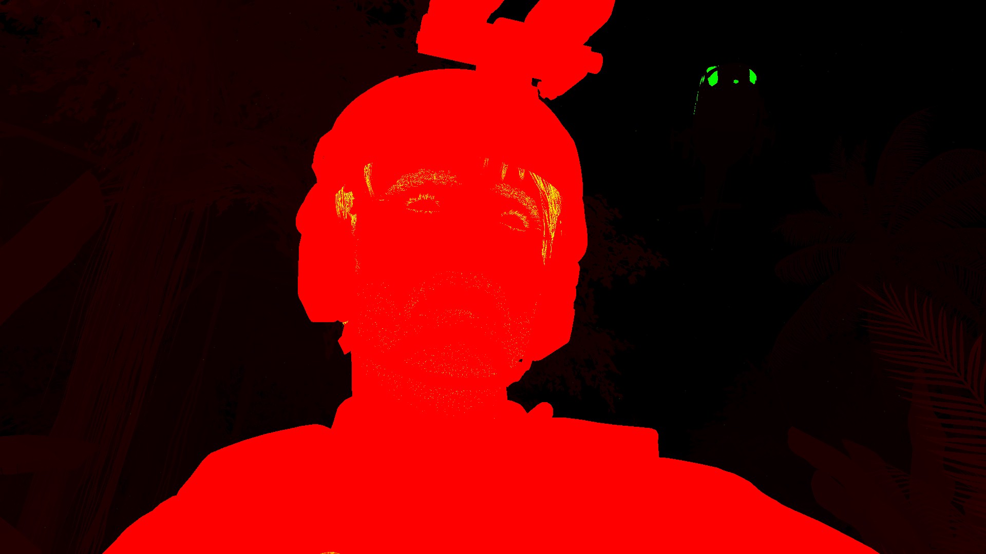
Character Shading
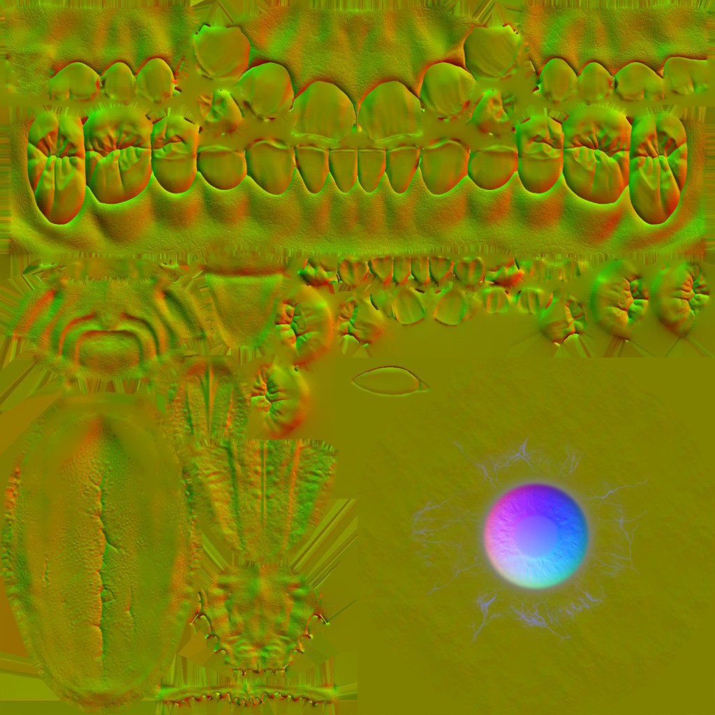
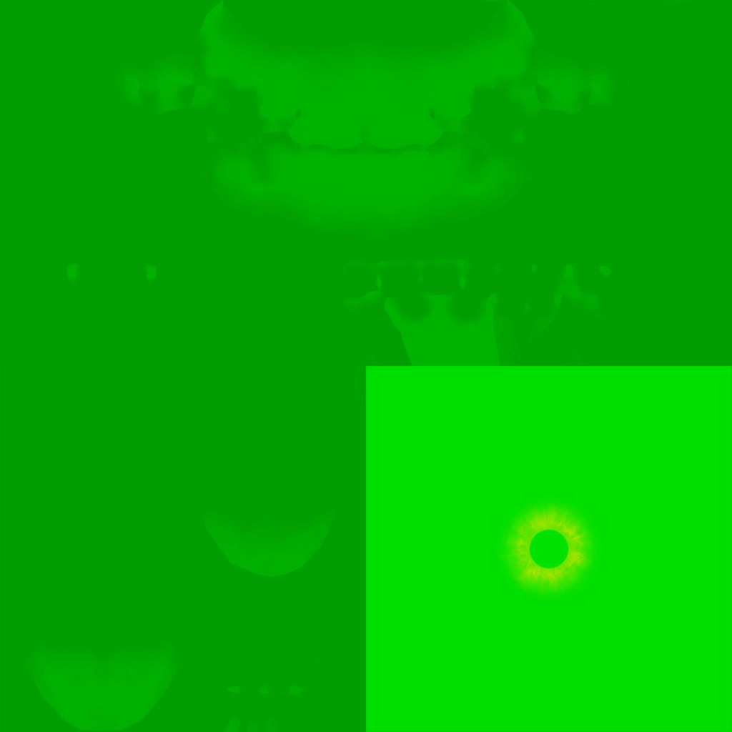
Once the regularly looking diffuse is ready, it comes the time to start boosting it to a higher level of beauty. This process starts with a dedicated pass for Eye & Skin shading. The pass starts always with the eyes, each pair of eyes in a single drawcall, so if there is 3 characters across the frame, it’s 3 draw cmds (6 eyes), if 1 character, then it’s 1 draw cmd (two eyes). Followed by a sequence of draw commands for each piece of geometry that is a skin or should look like skin. Let’s dive into some details.
1.Eye Shading
Involving some Linearly Transformed Cosines distribution, the eyes shading goes as follow.


And if not clear the actual impact of eye shading on the diffuse light output, you can take a closer look below.


And for few other examples, Feel free to check the inputs & full details foreach example in the collapsed tabs below the examples.


Example 2


And for a closer look


Example 3


And for a closer look

Example 4


And for a closer look

Actually this example doesn’t have a single shadowmap as every other example, this is a very large open map, so the sahdow map was split into multiple targets that includes a sun compartment as well as long distance shadow map.


Example 5


Because it’s 2 eye pairs, so i put the none-shared data for the 2 different commands, but put final output for all eyes. Also where Aleph & Axis still make sense in rendering the frame, but SkyVis & Terrain are absent due to the nature of the interior scene, and hence solid black are passed (red SkyVis mean solid black, because it’s a BC4…aka single component)
And for a closer look…


Multiple eye pairs, means multiple cmds!
In general, i’m not a very big fan of the textures utilization here, textures used for shading could be packed in a better way, for faster access and less memory. Yes there are shared resources between all draws from different characters, but those could have been “less” resources, at least the ones tagged “Eye Teeth”.
Apart from that, all examples that i’ve ever met during my sailing in that game, was including an extra 1*1 black (well, placeholder) for the teeth (as you might have noticed, all eye textures are the ones used for the teeth as well), that is called “Teeth Incandescene”, and it does nothing (as far as i can tell) beyond it’s name that implies some boosting functionality that was there, or planned to be there!
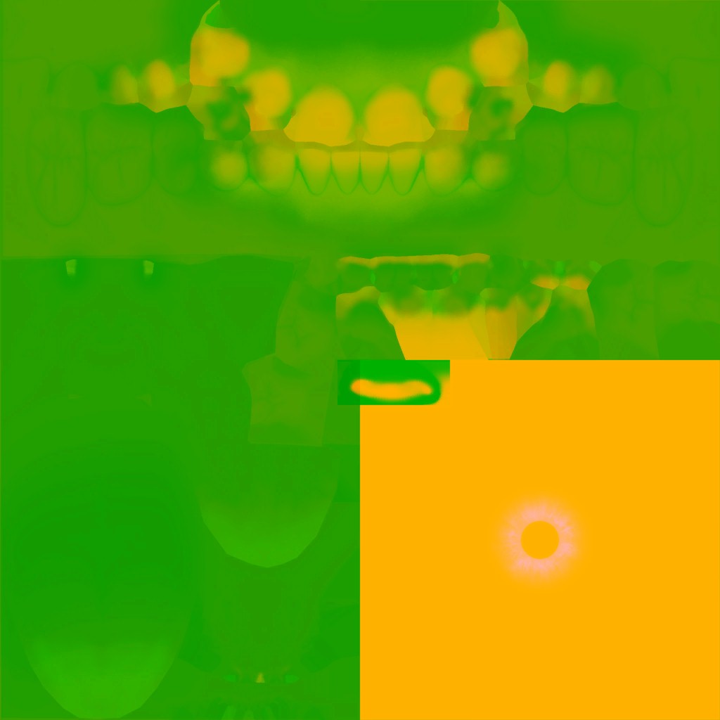
2.Skin Shading (SSS)
Nothing fancy, the rest of the pass is full of draw cmds with the count of the meshes that has SSS support. Mostly this is skin simulation, but at some cases this can include other meshes, for example the tongue & teeth for the cinematic version of most of the characters, such as Sam and president (even if that tongue & teeth are 100% hidden inside the mouth), or other meshes here & there.


And regarding the mask’s channels


And for another example, things are consistent…


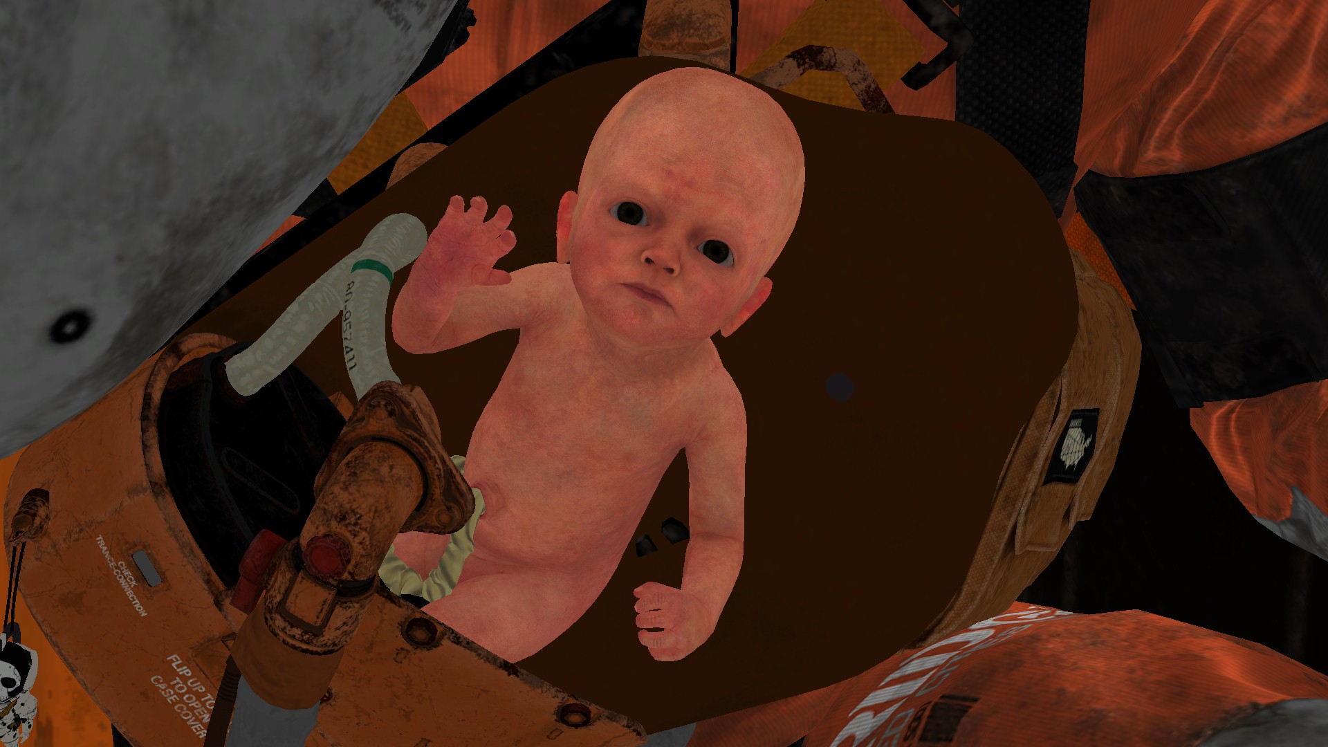
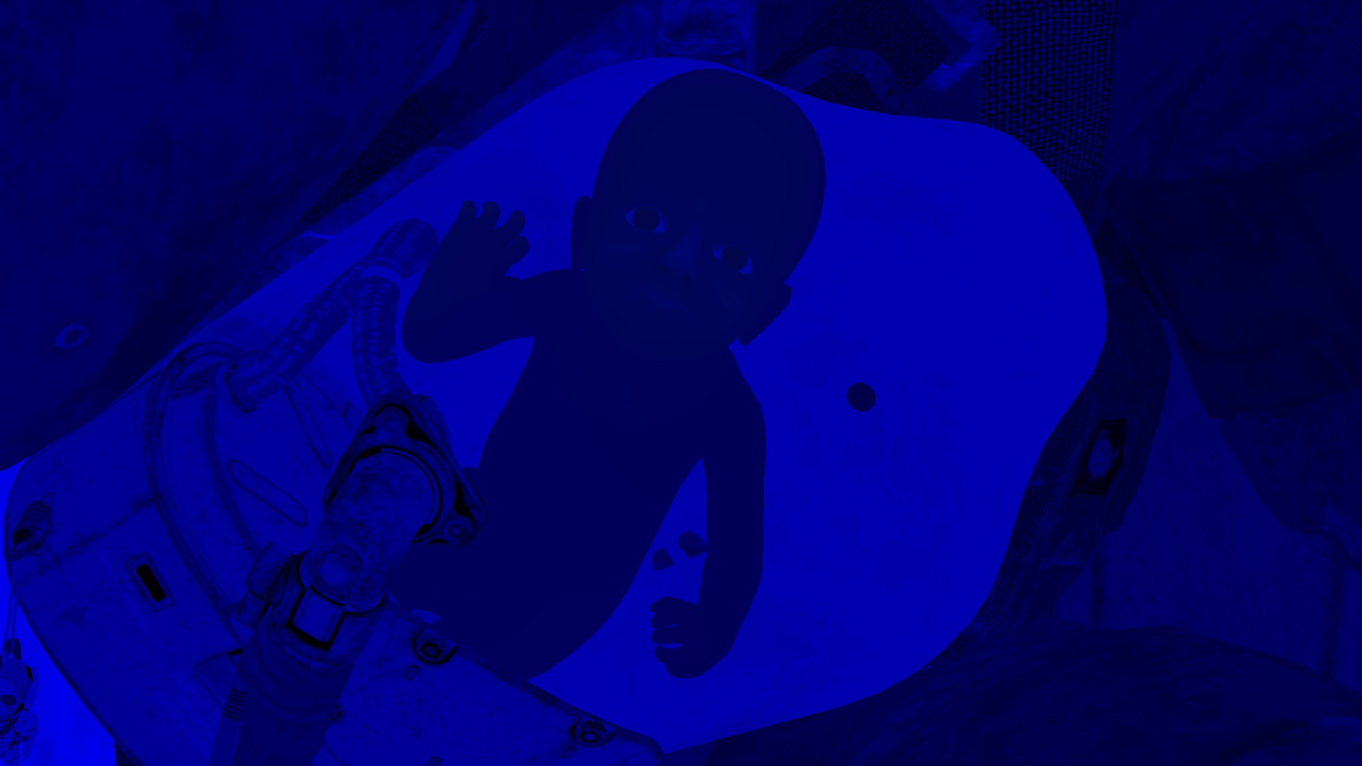
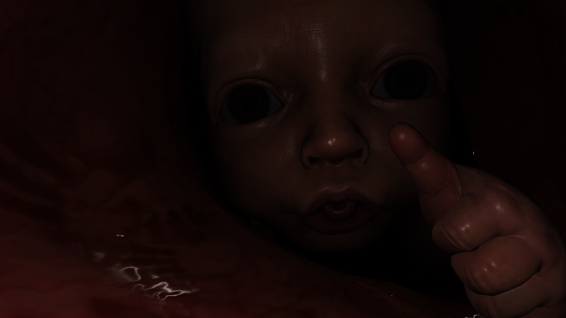
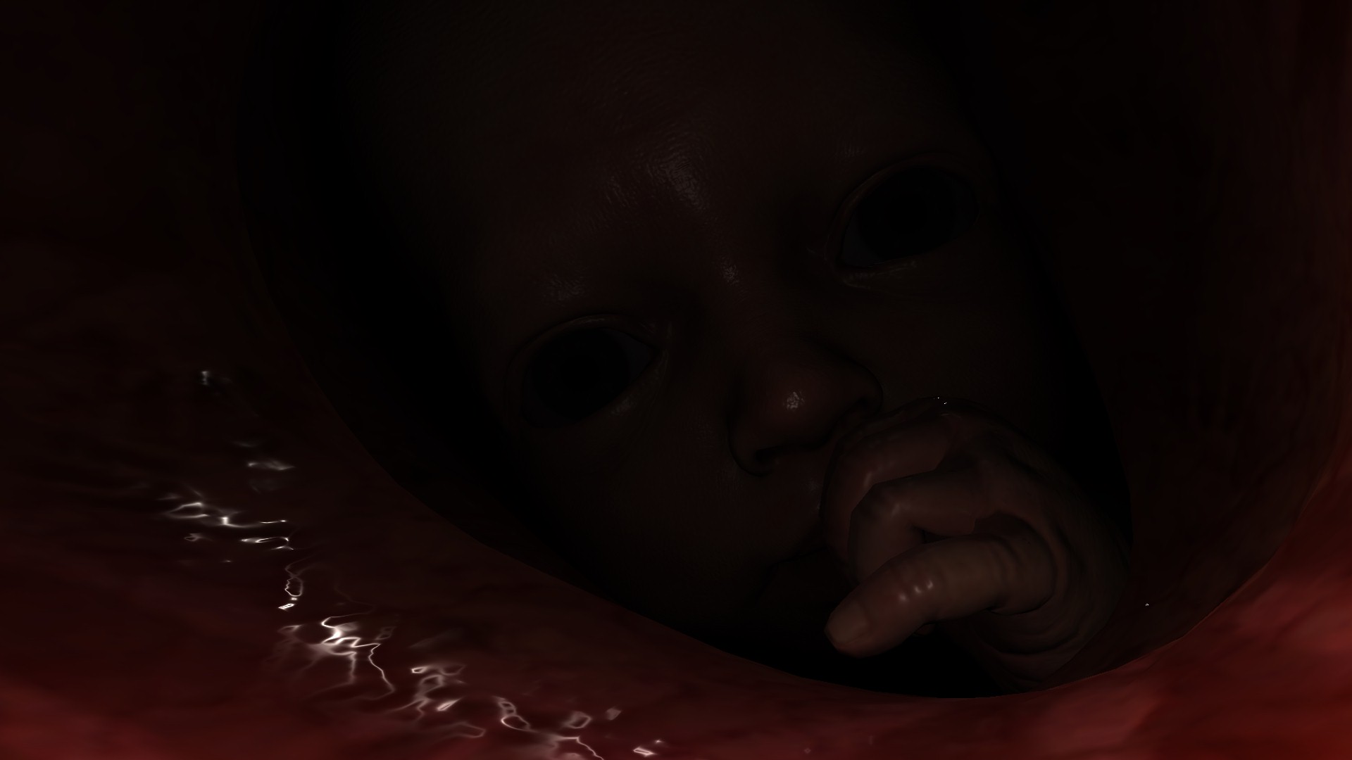
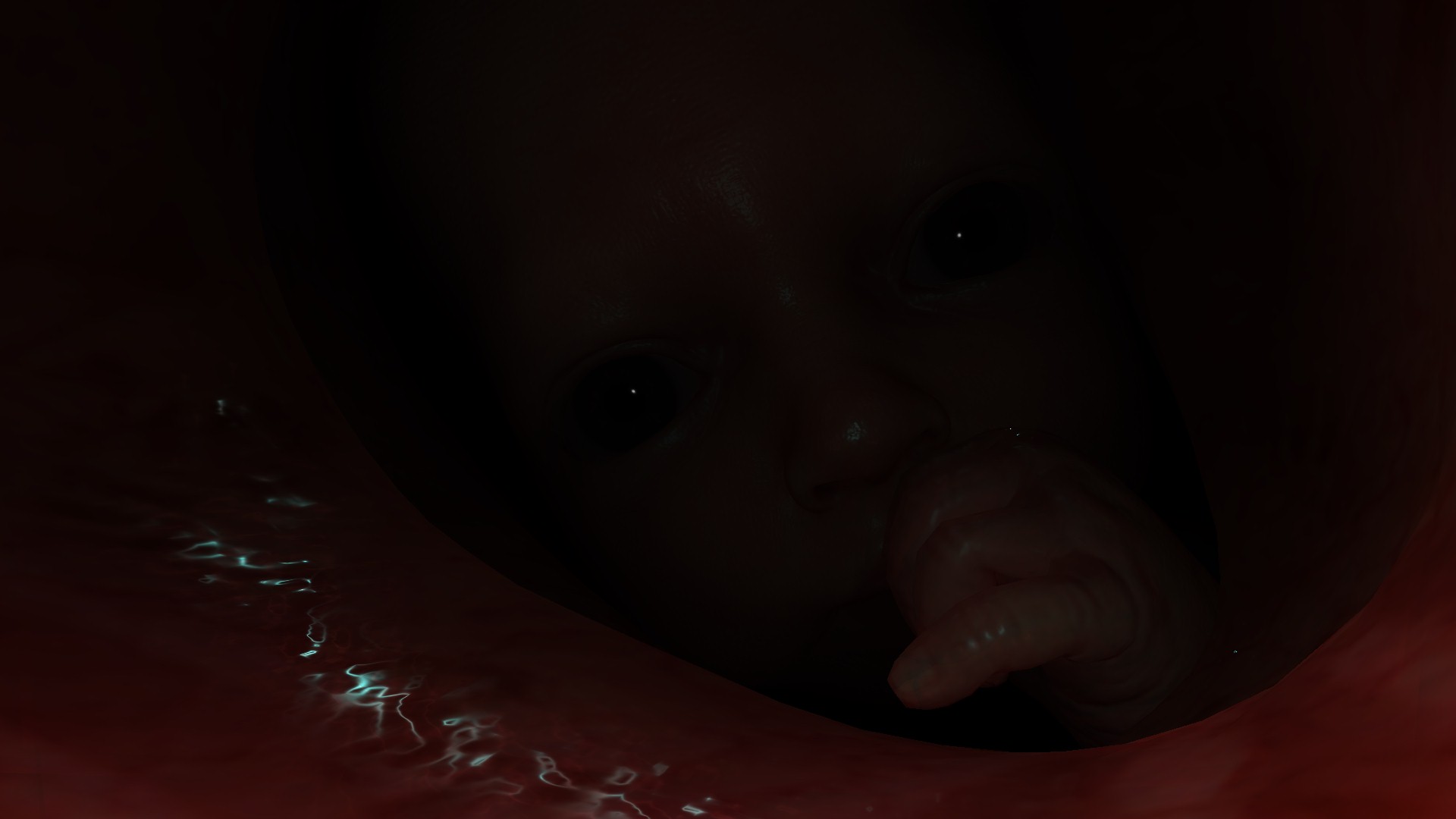
For cases such as BB things are different, because the entire frame is actually skin simulation. Not only BB full body, but also the womb as well entirely, and at such case, there is no skin masks passed during the rest of the skin renderpass, and it is enough to be replaced with a 1*1 solid black texture. Which i personally find a good optimization.
The reason i liked seeing this single 1*1 across the entire frame lifetime of any frame from DS, is that in the past (without mentioning a game/company/engine name) i worked in a AAA game/engine, where artists in such a case “have to” pass a solid black that “must be” at the exact same “unified” size for the character texture set!!! At this case of BB, that would be a 2048*2048 solid black, if BB made of two meshes, Head + Body, this means 2 different texture sets, and this means 2 different solid black 2048*2048 for BB only! So imagine every model in the game that doesn’t need a specific texture in it’s set, that gets a “unique” solid black 2k or 4k texture…And that was due to the laziness of applying changes to a very old Engine code, but at the same time the continuous rejection from producers in doing any improvements that is not part of their features production plan!
That game failed badly!!! (not for technical reasons though)


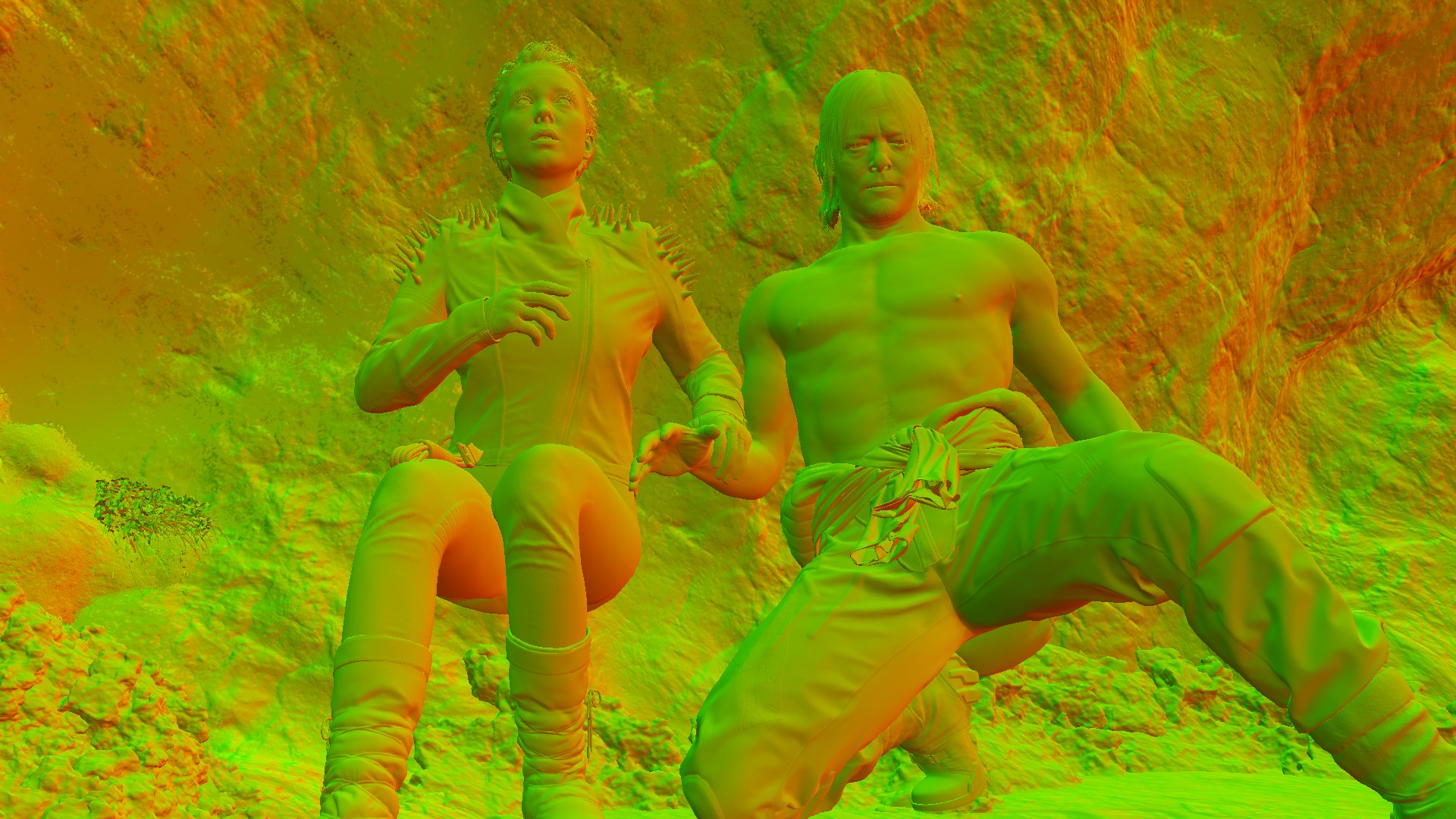
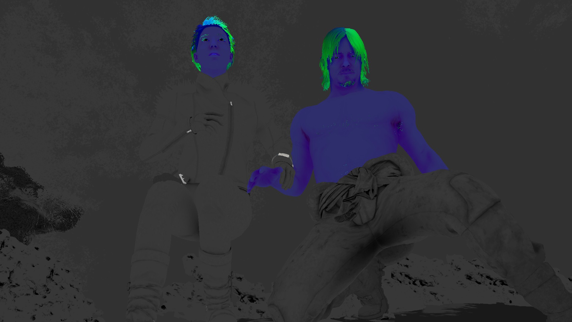
And for the sake of variation & penalty of skin thickness variations, here is a frame with 2 characters, that has much more interesting details due to the strong sun-light


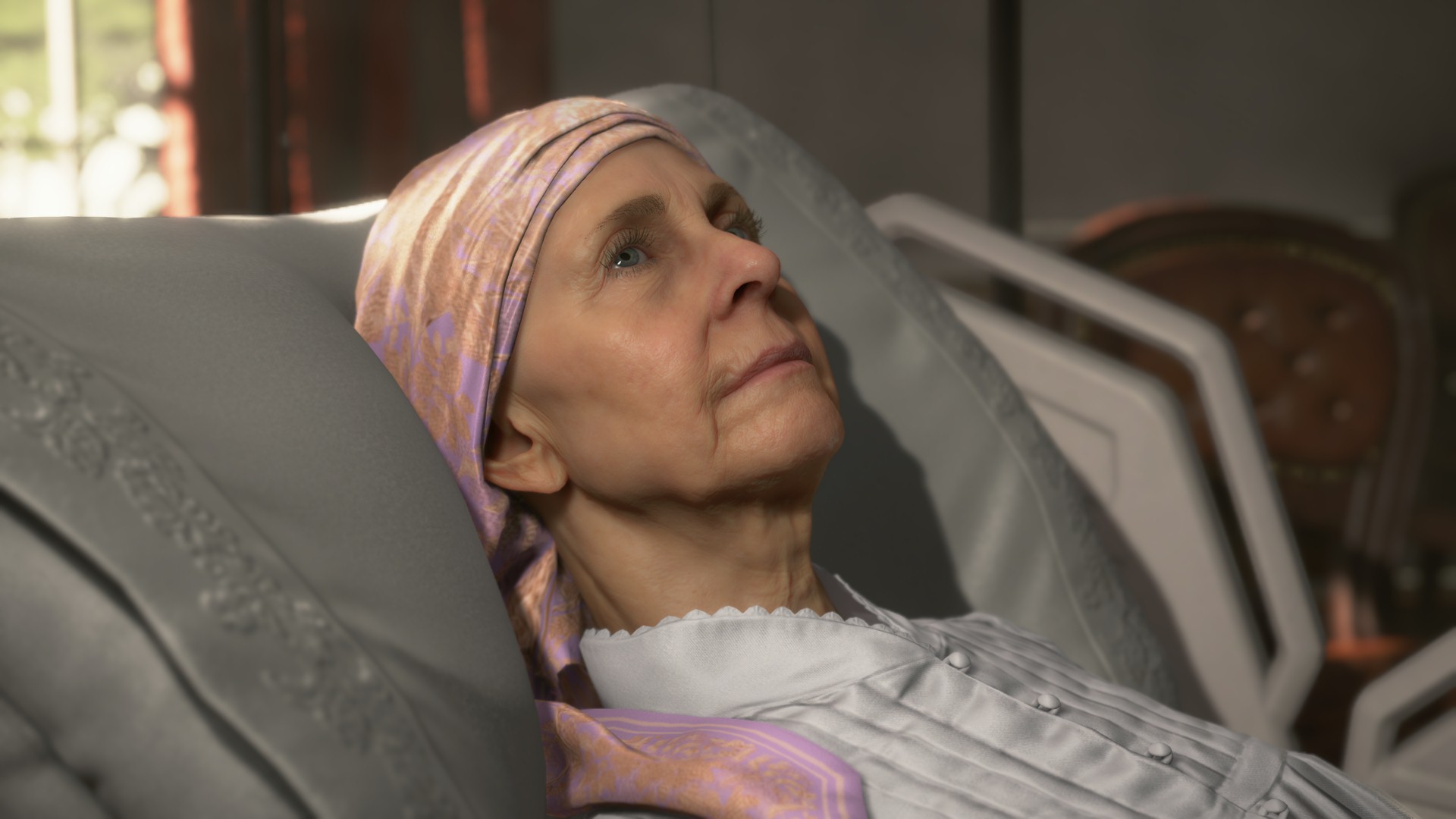
Unfortunately in this process, the one thing that i found a little annoying, was the burden taken to simulate skin for some hidden skin parts. For example, in the at President frame, the entire feet (covered by the blanked anyways in the full shot), as well as parts such as the chest (which is actually covered 100% by cloth) are being processed as skin shaded parts. The fact that the entire legs & feet is rendered and shaded in that frame, makes me wondering a lot about culling in Decima!
Thankfully that is not always the case, for example in Deadman’s(Guillermo del Toro) frame example 5 (mentioned previously at the eyes section), only visible skin is processed (head & hands), but this is not because of anything smart but there is no polygons under his cloth!! (check Guillermo’s mesh at the left side of the shadowmap view)
Anyways, while i like the overall quality of DS, and i do like how realistic the characters are, but i can’t stop myself sometimes from thinking about their skin as more tending to be made of wax or plastic than being made of flesh!
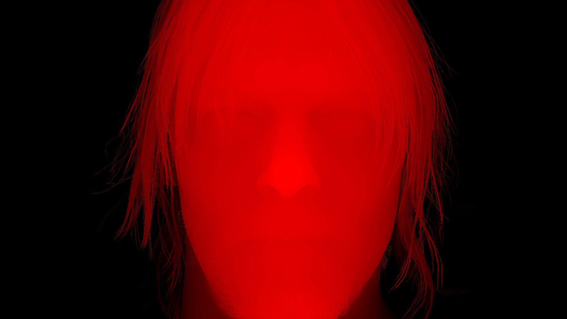
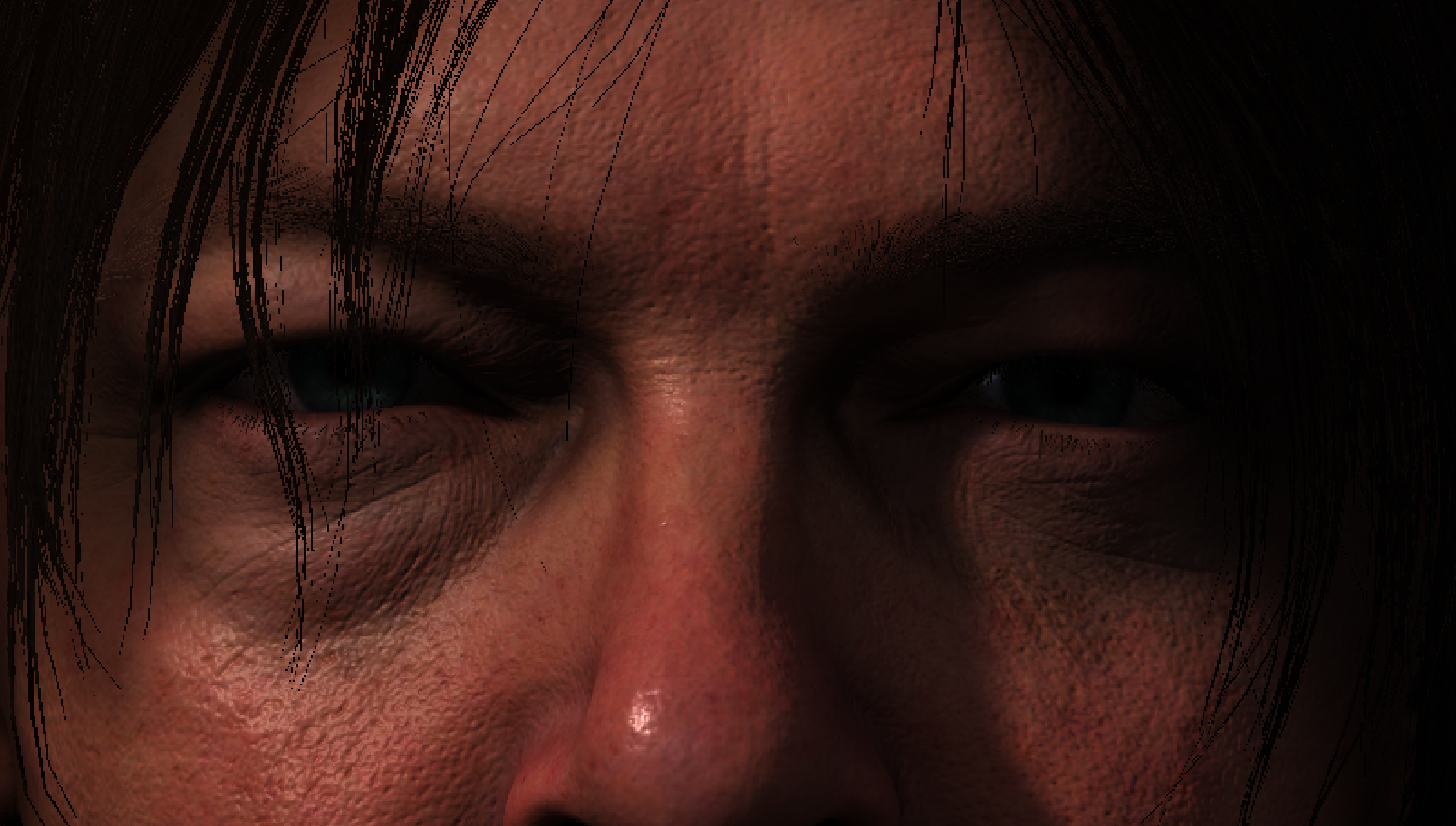
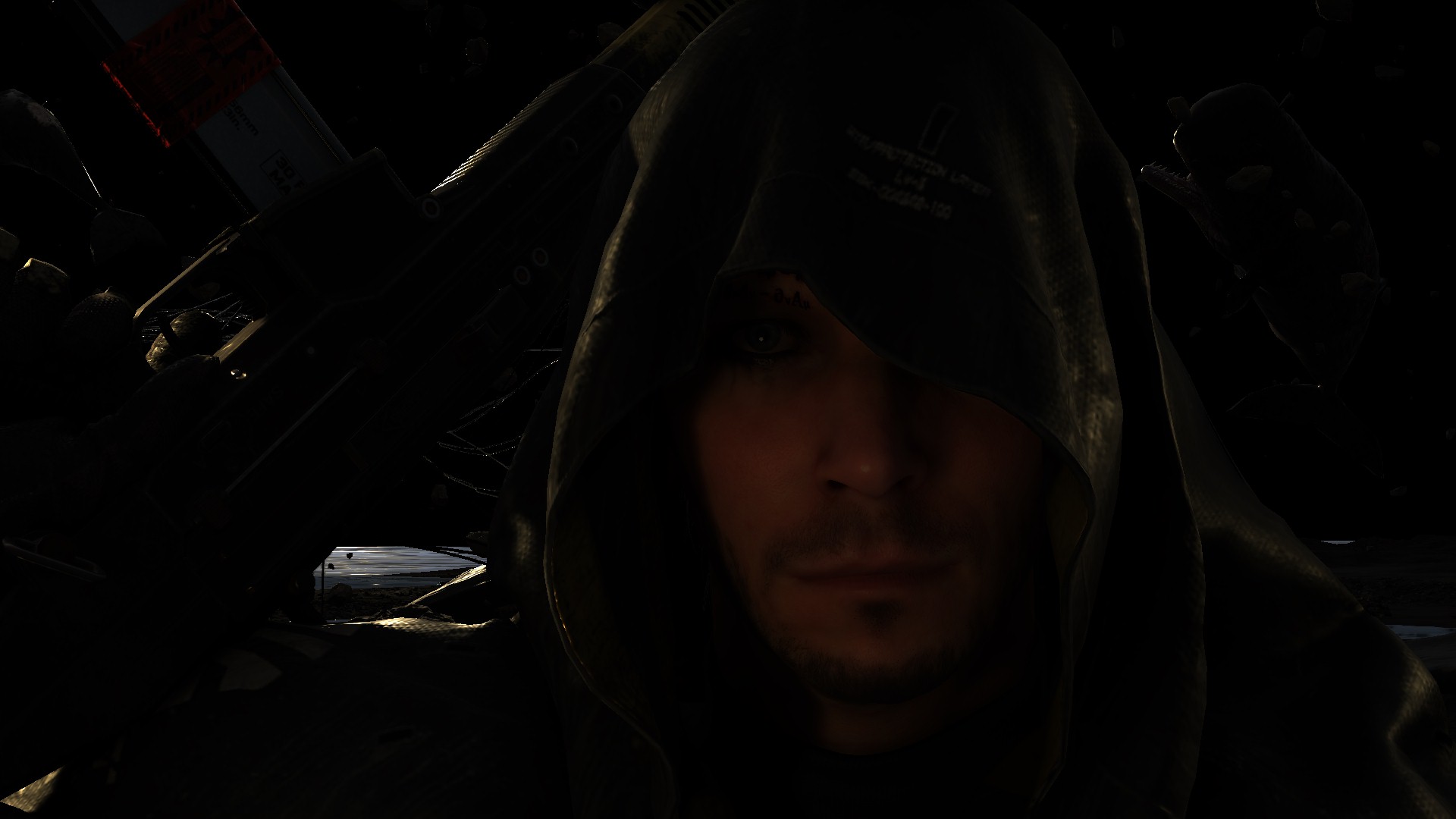
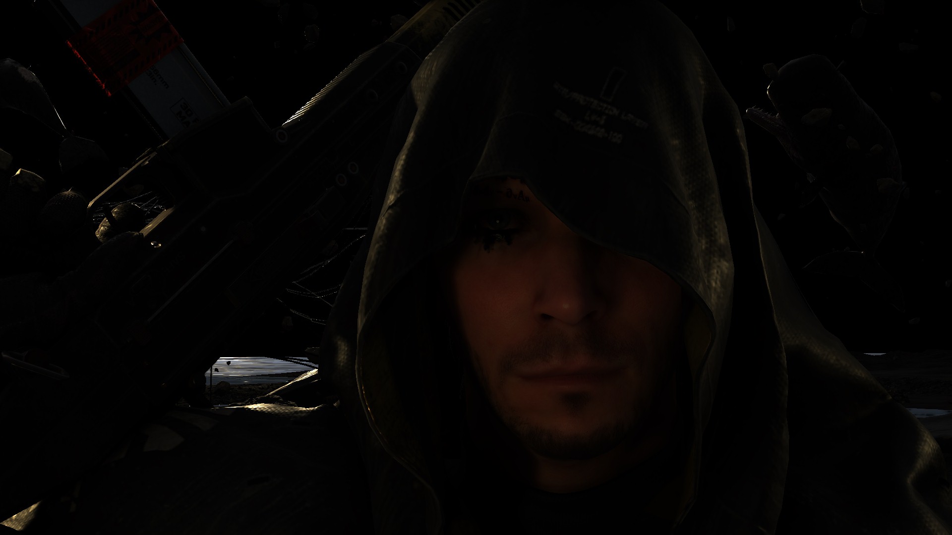
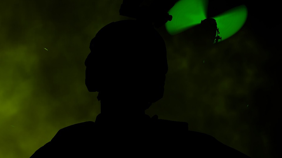
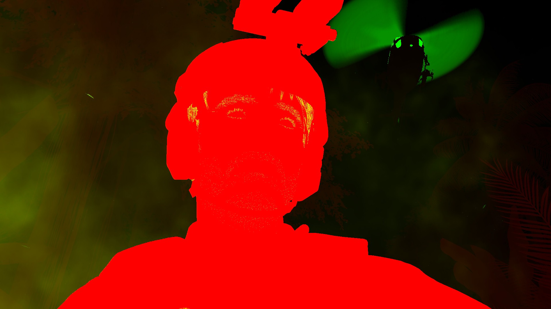
Eye Shadows + Tears
Shadowing eyes is usually part of the “realism” package for any AAA game seeking that direction, and here, in DS, shadowing eye is just brilliant. Not because of the shader or the technique or anything, but because the use of the viewport scissors. Yet, i did not see that been utilized in that way at any other engine. The idea is very simple. Just right before shading an eye, a piece of the frame is defined as the work area, and then the pass runs only for that area. The selected area is still not that ideal, because it is very large comparing to the eyes, or even comparing to the entire head that holding the eyeballs. So, for every eye pairs in the frame, a rect been decided, and used as scissors for the viewport.


The scissors are seem to be based on the distance from the camera though. So at certain distance, scissors are not used, and fullscreen viewport is utilized. But most of the cases, you’ll find them..
I do love scissors, and i do abuse them a lot, if you’ve seen my Mirage before, you would’ve noticed that, specially in the viewport debugging (let’s post a marketing video for my latest freak engine). You can watch many videos about it here.
Here at this step, we’ve an entire renderpass that is dedicated to self-shadowing the eyes (mostly by the eyelids or face wear) and putting tears if exist. And oh boy, this game is full of tears! And of course, if there is no tears (none-Reedus) it’s only short & sweet renderpass to only shade existing eyeballs across the frame.


The inputs for that renderpass is pretty much the same ones used earlier with the Diffuse Light renderpass (BRDF, GGX, Shadowmap, Normal, Cubemaps, IV,…etc.)
As you might’ve noticed, teras are not only the “regular” tears. The ink ones with the game’s theme are “most of the times” are treated as regular tears as well, but not always. For example, the teras at Cliff’s face is just part of his facial texture that is used in the deferred’s GBuffer pass.


Prepare for Sky Shading
Downscale Diffuse Light
Nothing very fancy to show up here, just take the final Diffuse Light output with all flavors (Eye Shading, SSS, Eye Shadows, Tears), and scale it down to half (from 1920*1080 to 960*540) while setting the format of the new 1/2 rendertarget to RGB10A2_UNORM from RG11B10_FLOAT. This is to be used later shortly…
Sky & Volumetric Fog
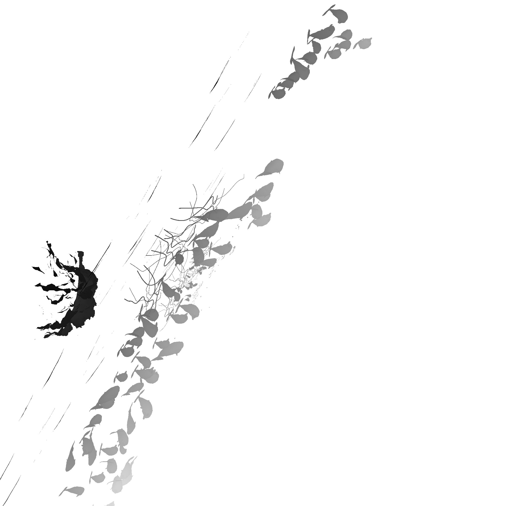
Hair Mask
This is an entire renderpass for hair (and thing objects) drawing. Now you would say hair is already drawn, and we can see it in the past few step already, so what’s different going on here?
Remember the very red rendertarget, the one holding the 1/2 depth and the blend (halfDepthBlend), now this one’s data get carried over to a full target size render target 1920*1080 of the format RG16_FLOAT, we do still have the depth in the R channel, but then the G channel will be holding all hair data. So any hair type of mesh (mustache, beard, eyebrows, eyelashes,…etc.) get re-drawn again, not only to boost the thin hairs, so it become more visible, so later in when applying AA they don’t vanish. Hairs are stored as well in a form of black/white mask in the G channel of the “Depth Blend” rendertarget (not half Depth Blend anymore). This G channel will be used shortly in the post-processing with the DOF as well as AA, in order to make sure that “individual hairs” not loosing their “thickness”. So… you can say that the reason behind his Hair Mask renderpass is to make sure the game can boost the thickness of the very thing and tiny details, which is 90% of the time is hair.
So with some hair textures like those
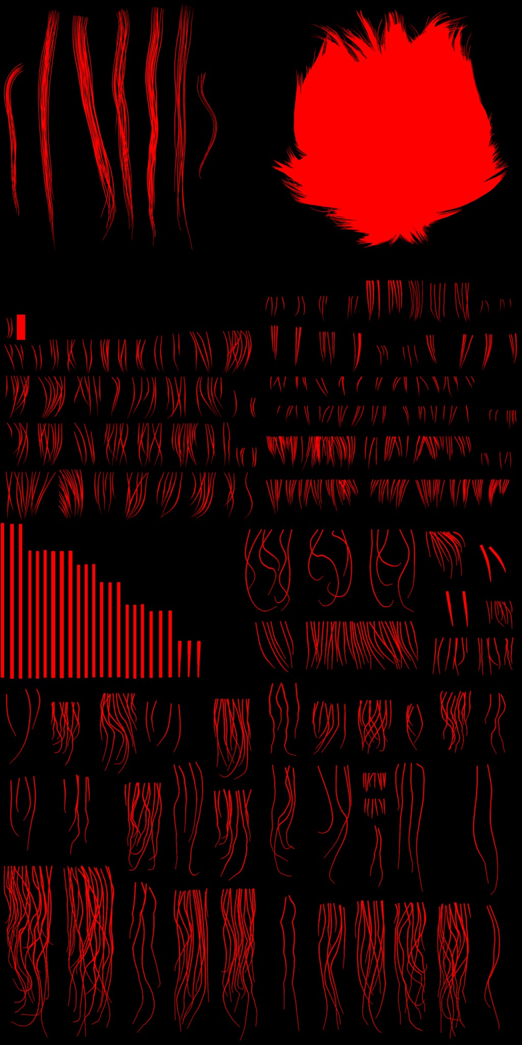
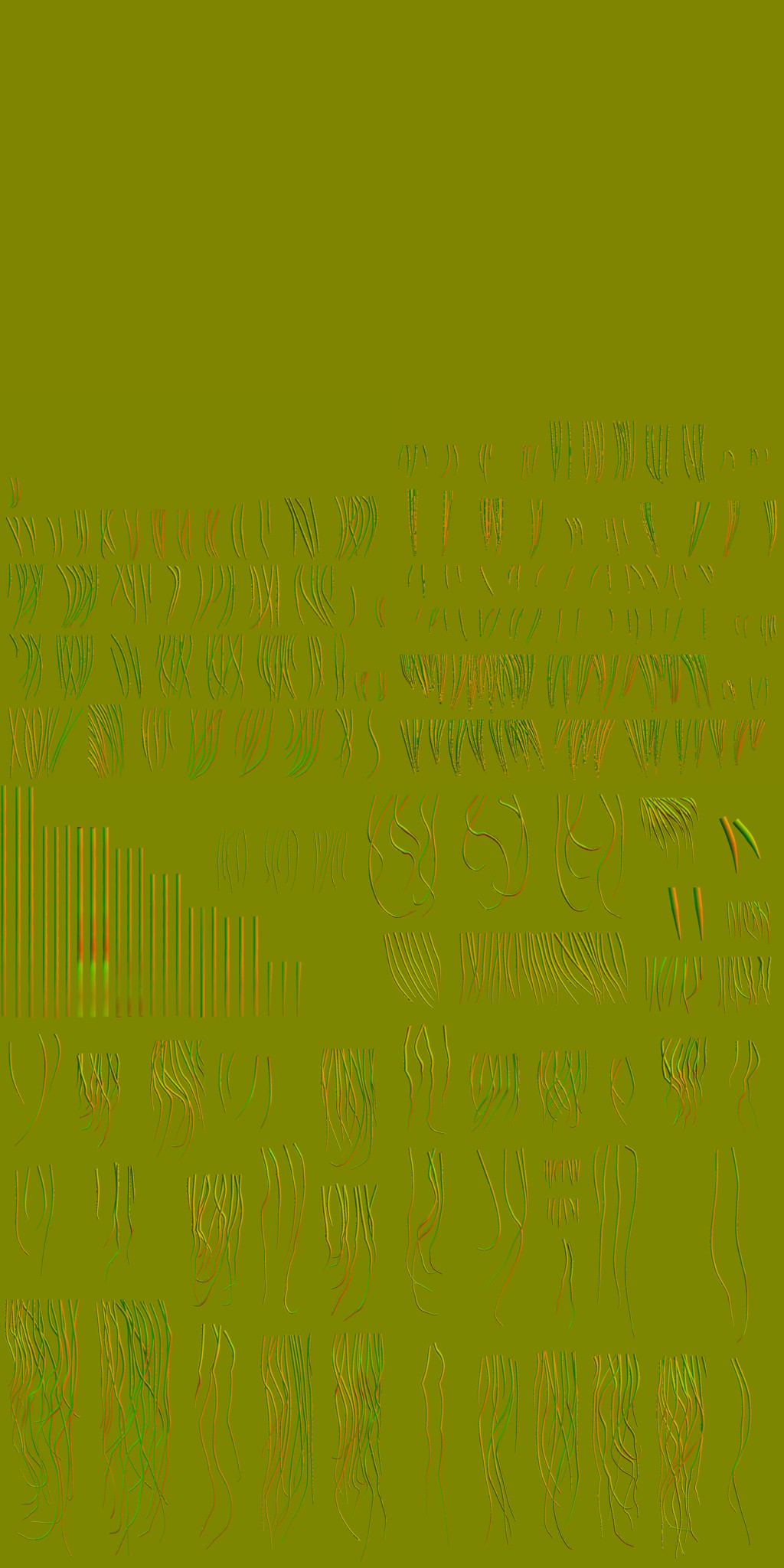
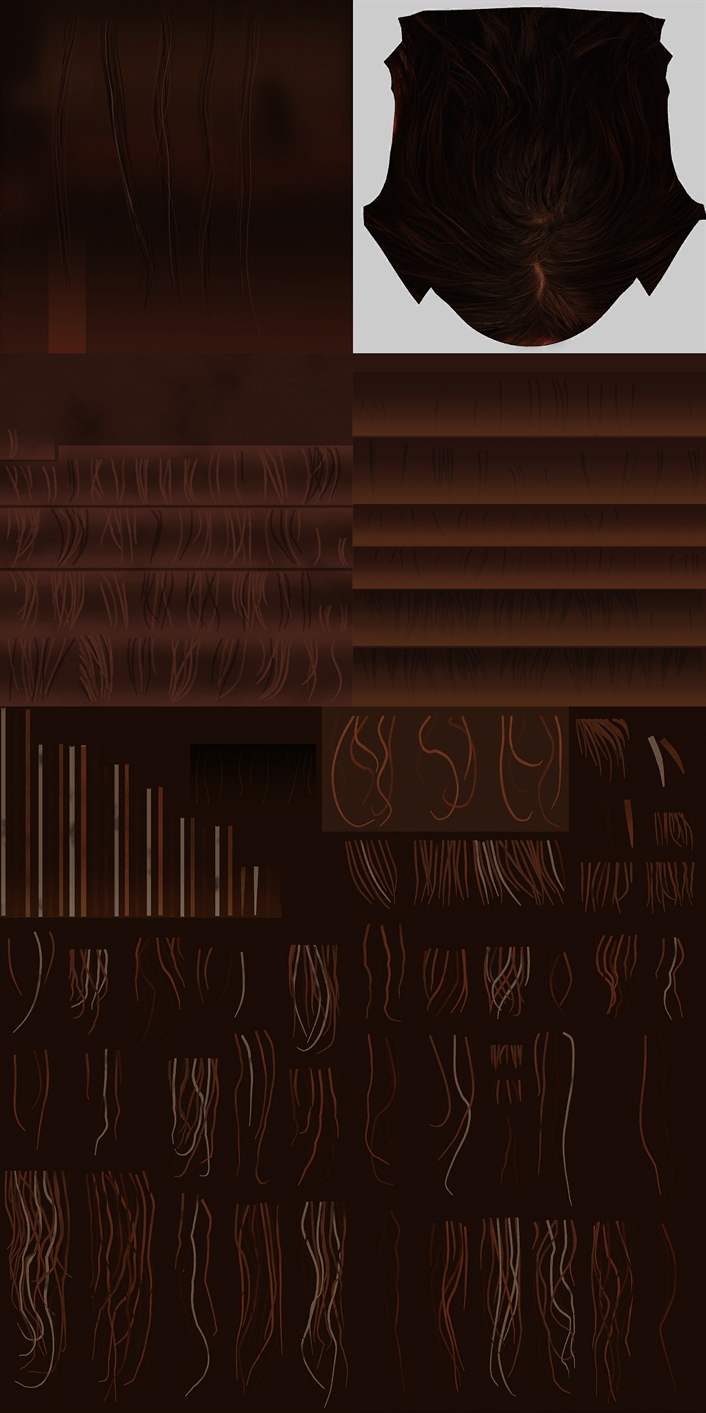


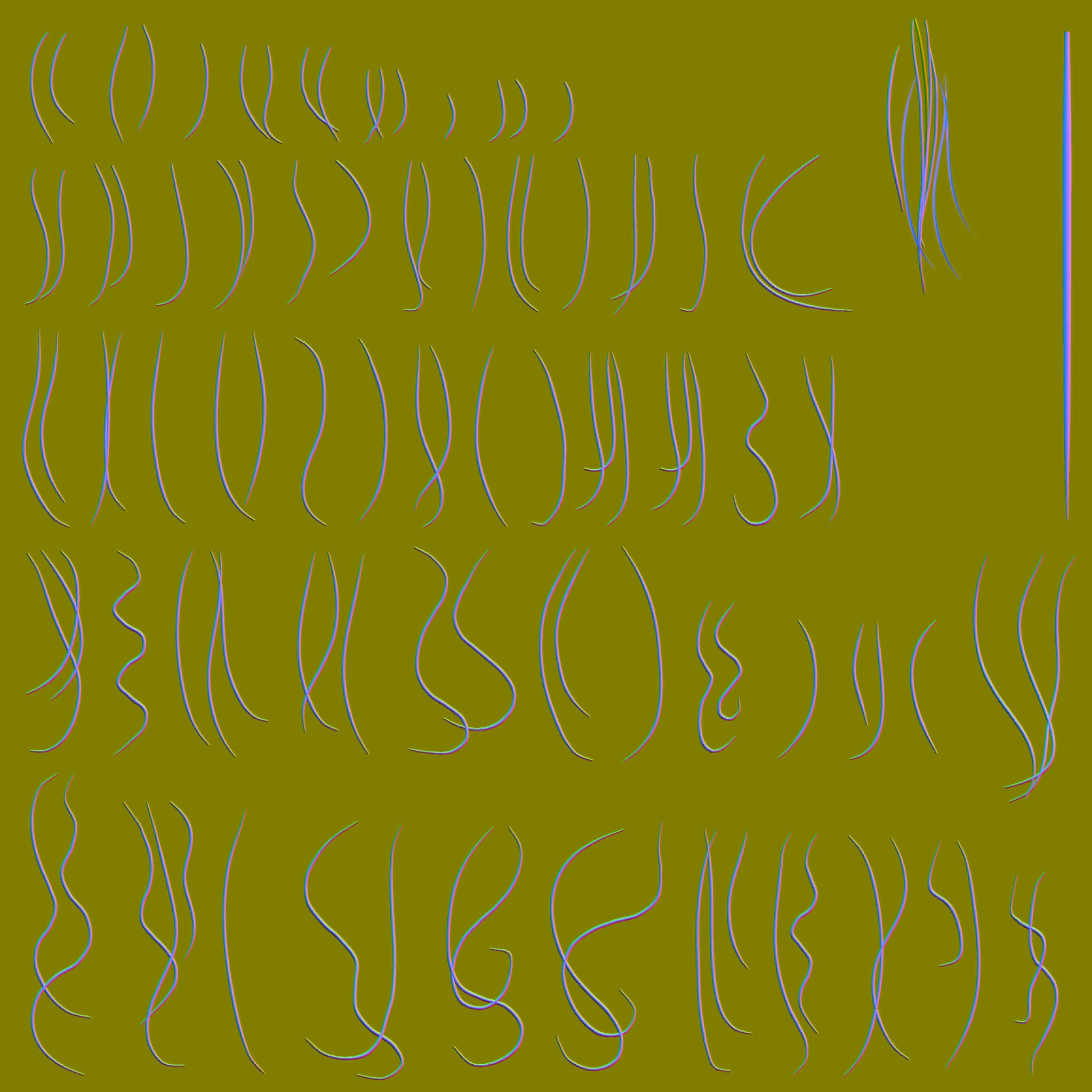
there is also a “Fake Specular Ramp”, i did not put it alongside the others, because it makes the gallery very tall. So you can check it here if interested.
Draw cmds go step by step for all the hair (very thin) objects/meshes that are exist in the scene, in each draw you get two 3 outputs, the modified Diffuse (that has sss, tears & everything accumulated from previous steps), DepthBlend Mask, Depth

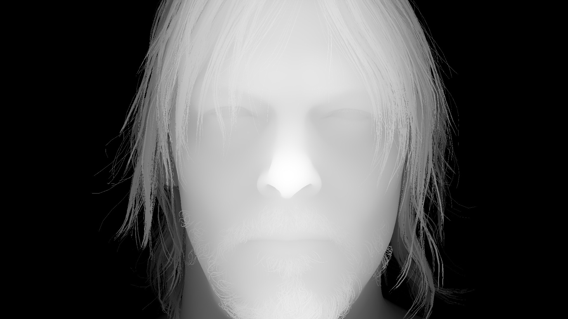


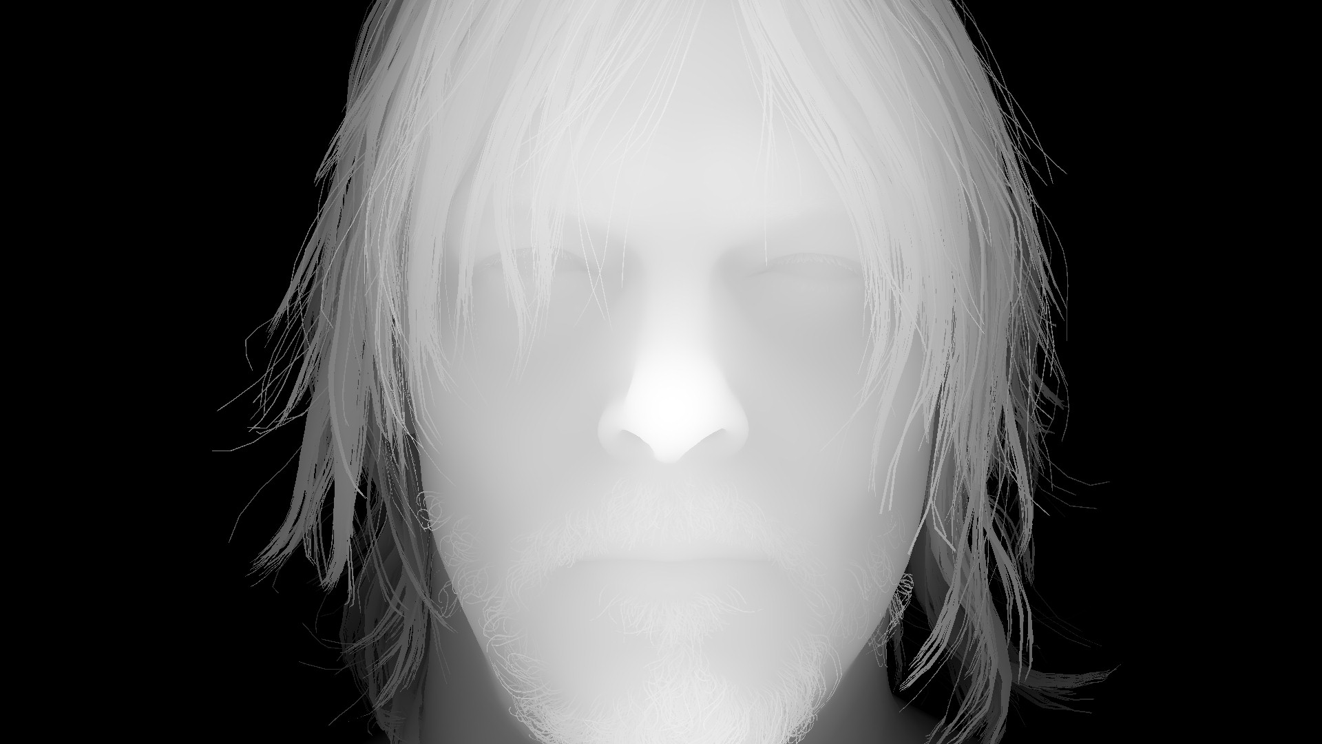


protected from vanishing later
And another example with more hair & multiple characters, still same idea..and always, last draw have some fine particles


Can even observer the very very fine hair details at the chest by the end
i like this step, because it gives me the opportunity to find out some interesting stuff, such as the tiny tiny beard Cliff got, which is hard to see even in a very very close up!


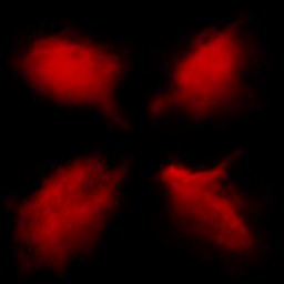
And regarding the very tiny particles that are drawn most of the time, there is a nice smart single 256*256 texture or the format BC4_UNORM that is used for that purpose. i call it smart, because it has the same particle in multiple directions with slight shape difference, which makes it easy to make variations without the need to transform each particle randomly!
Copy & Clear
Yet another ClearRenderTargetView()
Forward Pass[es]
Without a question, there is always at least a single forward pass running, but most of the time, there is 2 forward passes, and yet i never found more beyond that. Where the 1st pass is all about translucent and semi-transparent meshes, the later one is mostly about some transparent effects such as smoke.
This is not the only difference between both forward passes, but the core difference is, where the Translucency forward pass is drawing right away into the current Diffuse output, the later pass is writing to a new rendertarget that is called “Forward Buffer”, as well as to a “Full Resolution Depth Blend” that is similar to the previous 1/2 resolution Depth Blend that we discussed earlier. Those 2 rendertargets are kept for later compositing.
The other final difference, is the Blend values/Masks where during translucency is drawing into a Full Res Depth Blend rendertarget, at the later pass, it draws into a 1/2 Res Depth Blend rendertarget.
Drawing at this phase, regardless it is into the Diffuse output right away, or into a new rendertarget, it all happens similarly to everything been drawn at this point in a PBR fashion, with the use of the exact same set of textures that are used earlier (Cubemaps, Aleph, BRDF,…etc.), with a slight addition, which is the Volumetric Light Volume Texture when needed.
1.Translucency
Drawing all the transparent/translucent meshes one by one right away into the current diffuse.
You would notice that there are some changes in the Hairs, as during this forward pass, there is another & last layer of the hairs (all hairs no exception, including chest hair, eyelashes, eyebrows,…etc.) that is semi-transparent, which is one more element in the formula of how to end up with cool looking hair such as the outcome in Death Stranding. The reason behind this translucent hair layer is, 1st it makes the hair more visible, and 2nd it does some sort of self shadowing, even if it is not a per hair-level shadows, but it does help a lot in the realism, let’s consider it as “fake self soft shadowing”. I would leave this frame as an example of hair, check it carefully, hair surfaces occupy a large space of the frame and i took it specifically in 4k.
In Level 3D UI
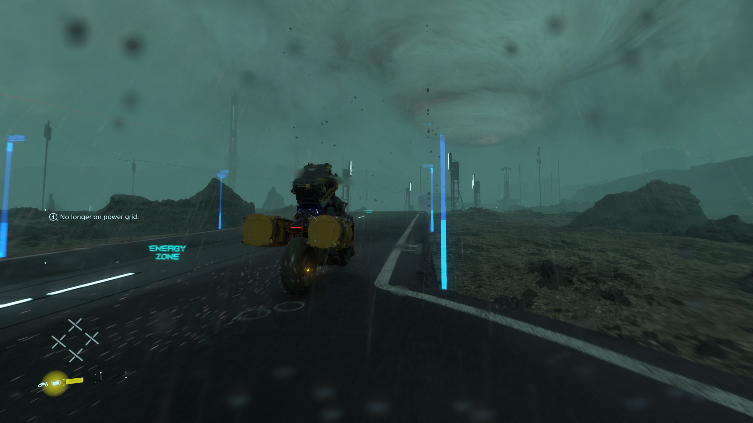
During the translucency pass, and perhaps by it’s beginning, any UI that is put in the world space as 3d UI surfaces, they got drawn in patched/instanced fashion as 3d deferred translucent surfaces, except that they don’t use that much of deferred textures, and enough to have some masks…just like UI (well, a regular game UI anyways is almost the same thing, except it is “sorta” in screenspace!). Maybe you’ve noticed that in the last example where Sam is on the bike and there are some 3d UI and text along the road
By using only a single 512*512 atlas, it can draw indexed instances for all the elements in batches like that..

And perhaps it’s much more clear when there is a lot more UI 3d elements, such as this frame


2.Forward Buffer [Not Always]
At this 2nd forward pass, mostly things that act like Big VFX that is not necessarily are particles systems, things such as lens dirt, smoke,…etc. Again, keep in mind, what is done here is not particle systems, but you can consider it a “special” case of particles-like objects.


Note
You might have noticed that i put here 5 examples only for this Forward Buffer renderpass, where i put 7 examples in the 1st forward renderpass (the translucency), this is actually something in purpose, because i wanted to give an example of frames (the 1st two examples in the Translucency) that has a single forward renderpass that is for Translucency, and they don’t have any form of Forward Buffer creation.
And if you prefer to see the progress of the Forward Buffer (as well as the 1/2 Res Depth Blend) you can check the gifs below, or just click on each to check a high resolution video on YT.


2nd row, Half Res Depth Blend progress
Lens Dirt [Not Always]
When it is exist, it is usually the last thing to draw in the Forward Buffer (you might have noticed some already in those previous examples), and the Lens Dirt is not applied in a form of a fullscreen texture as you would usually find in other games, the Lens effects here are most of the time animated, which makes a near-to-particles technique is a good work around it with the flavor of instances, so the game can end up with living dirt on the camera lens, instead of a fullscreen texture that will be hard to animate it’s components one by one or even patch by patch. In general, it is neat and looking nice, and it is not always the case to have Lens Dirt in a frame anyways.
And in action, and with even some over the time fade, it looks nice
What differ this lens dirt that is almost done in a particles technique, that they are way less in terms of amount or instances, and the lens dirt is drawn to the Forward Buffer, where particles (discussed below) is drawn to the frame right away.
And don’t let the lens dirt effect trick you, there are many many cases where what you would think is a lens dirt effect, is not actually lens dirt or even done during that short renderpass, take the two examples below, the dirt or wetness on the lens is actually GPU particle systems that is done during the upcoming particles renderpass (discussing shortly below), but they’re kinda particle systems that is sticks very very very close to the camera (sometimes even transformed as child of the camera), and after the DOF effect, they look, seem & feel just like lens dirt effect…But they are not!
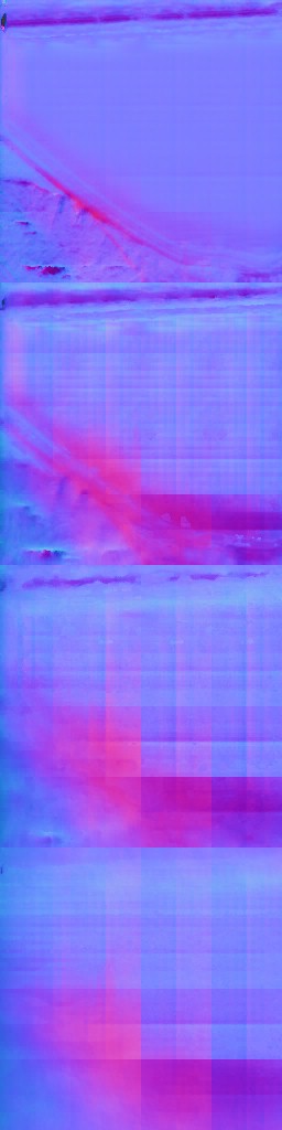
Motion Vector Texture Create
Motion Vectors are almost an industry standard by now, it is hard to find an engine or even renderer that is not storing Motion Vectors, which is needed for penalty of effects. To name couple that are in the scope of this article/game, and those generated textures will be used with very soon in few paragraphs, is the TAA (Temporal Anti-Aliasing) as well as the MB (Motion Blur).
Draw takes place one by one, object by object for every object that have velocities, ending up with a render target that is 1/2 of the target resolution (960*540 at 1080 target, or 1920*1080 at 4k target), of the format RG11_FLOAT .


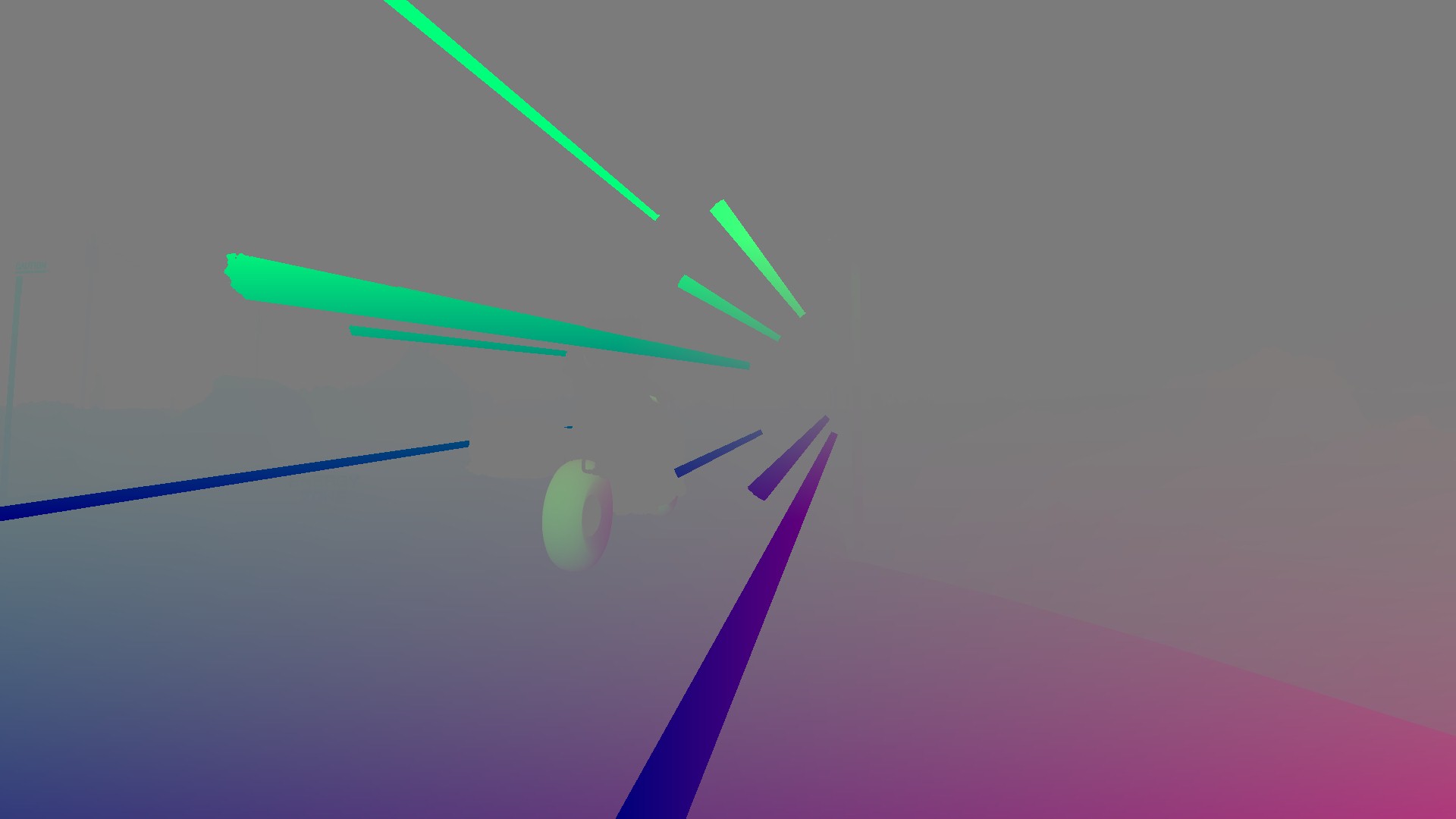
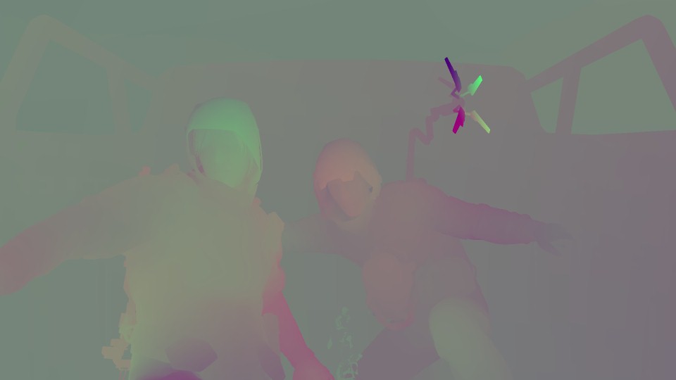

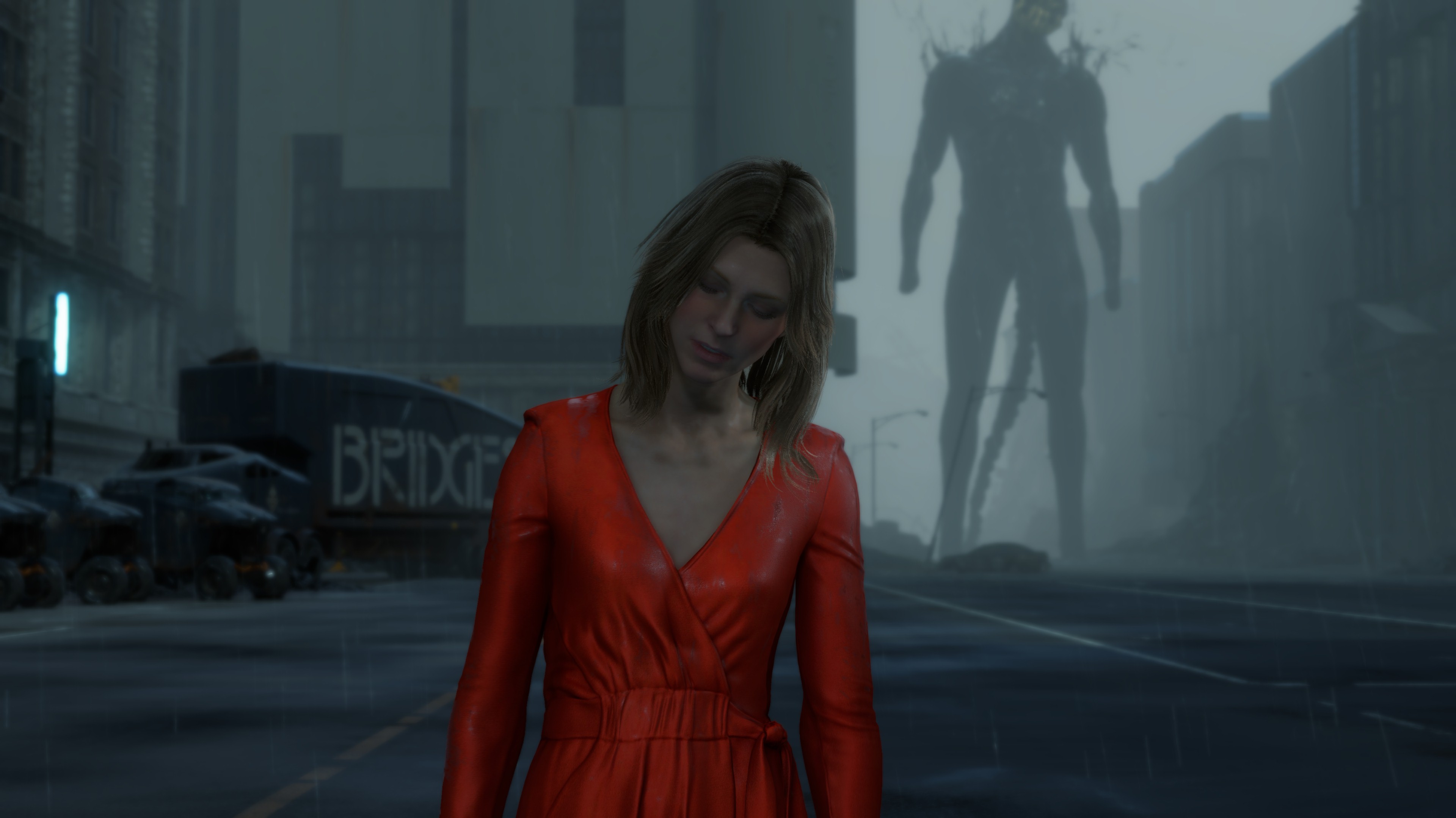


2nd row, the Motion Vector Textures are set into a proper range, for the sake of the article and for more clarification
Last row is just the Swapchains
Finalize Depth Blend Texture
So far you might have noticed that we’ve two individual Depth Blend buffers for forward data, one called Half Res Depth Blend Buffer Texture and the other one called Full Res Depth Blend Buffer Texture, and each has it’s own use cases as discussed earlier. Now comes the time to mix both into a single & final Depth Blend Texture that will be used shortly later as an input for some Post-Processing.


Despite the fact that this step is always present in a frame lifetime, but it’s output might not be 100% utilized. As yet i see it is used with DOF only, and for frames that rendering during gameplay, there is no DOF enabled, it is cinematic only effect as it seem, and hence the output Depth Blend Texture is not really utilized. So you can consider this step a little bit of waste at some extent.
GPU Particles
GPU particles comes in many forms that depends on the occasion. Where usually the frame will have a single pass that patch draw particle systems, there are other cases that are not common for a typical frame. But let’s see all those possibilities in the order of execution, if we consider that there is an ideal frame that have all happening at the same time (which is the case in some captures below).
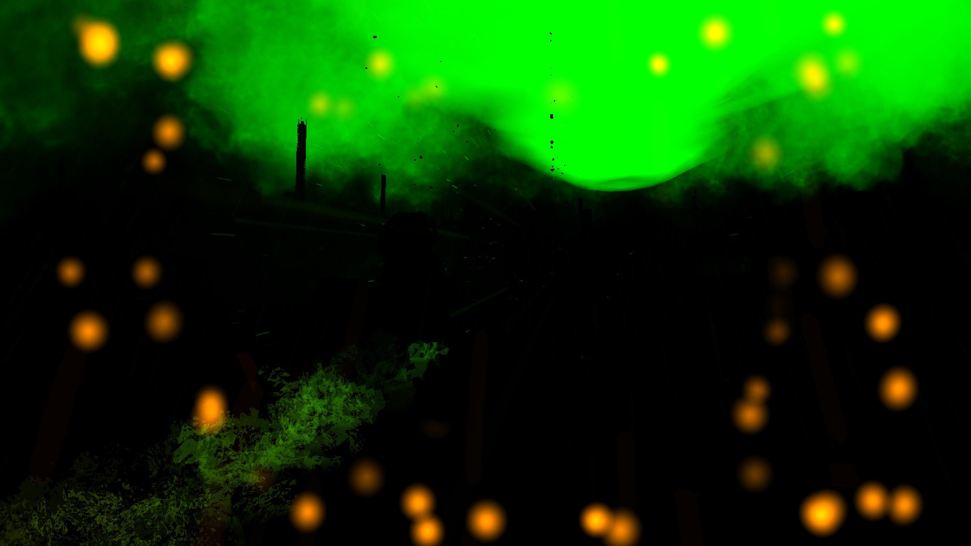
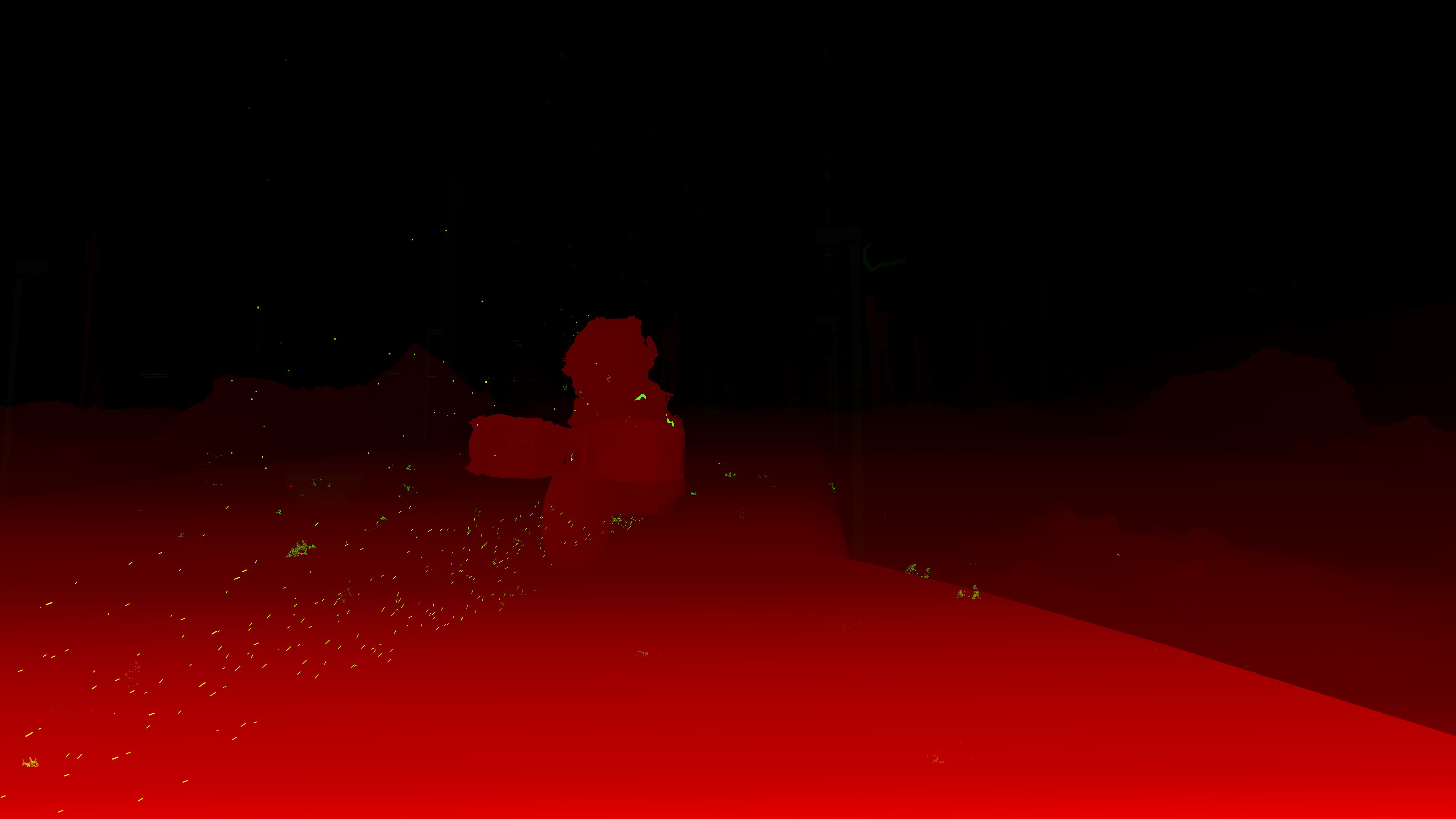
1.Markers (Static Particles)
There is no deny that the first time i played that game, and the moment i hit to Scan Terrain (the R1/RB button in the controller) i just liked what i saw. It could seem a simple trick that is made with some smart scripting + VFX, but the final visual feedback as well as the quality was quite satisfying for me, which made me flag it as something to check if ever dug that game. I think in terms of the game mechanics it is called “Scan Terrain” if i’m not mistaken, but for the sake of simplicity, i call it “Markers”.
Markers come very late in terms of drawing, as they seem to work as particles (not necessarily behave as particles, even though they are computed earlier), it is one of those very few late draw cmds that takes place right away before applying post processing. As a matter of fact, the Markers are the 1st thing to draw in the particles/VFX queue of commands, as everything after the Markers are particles until we hit the Post Processing commands. So absolutely those are particles, and those got their points baked/simulated to static positions very early at the start of the frame as any other GPU particles. So, you can call them “Static Particles” that can do billboarding once in a while…
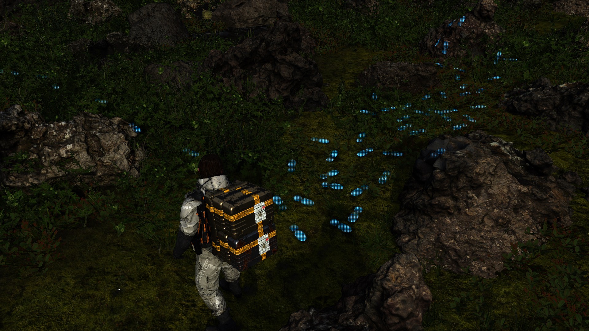
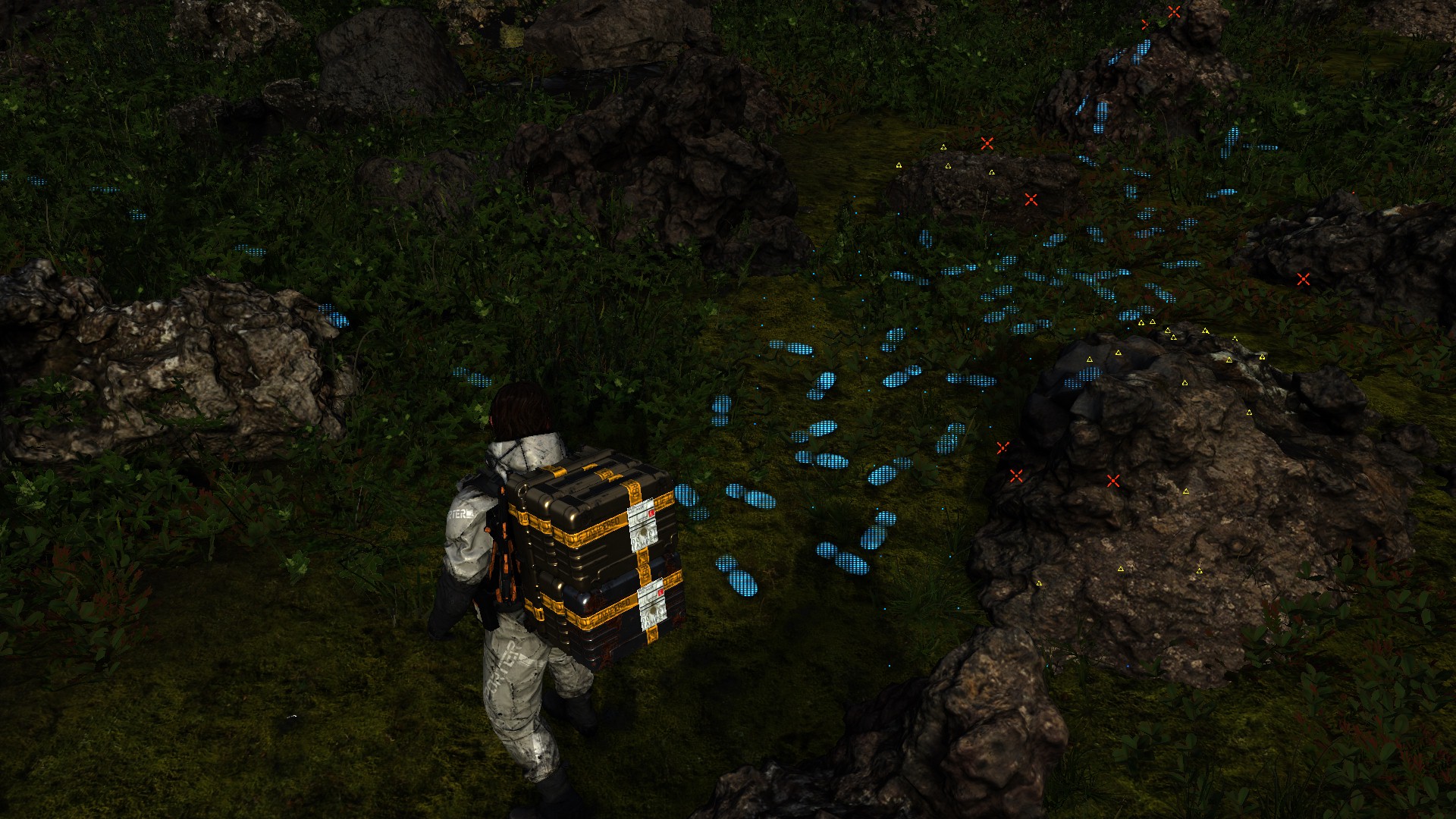
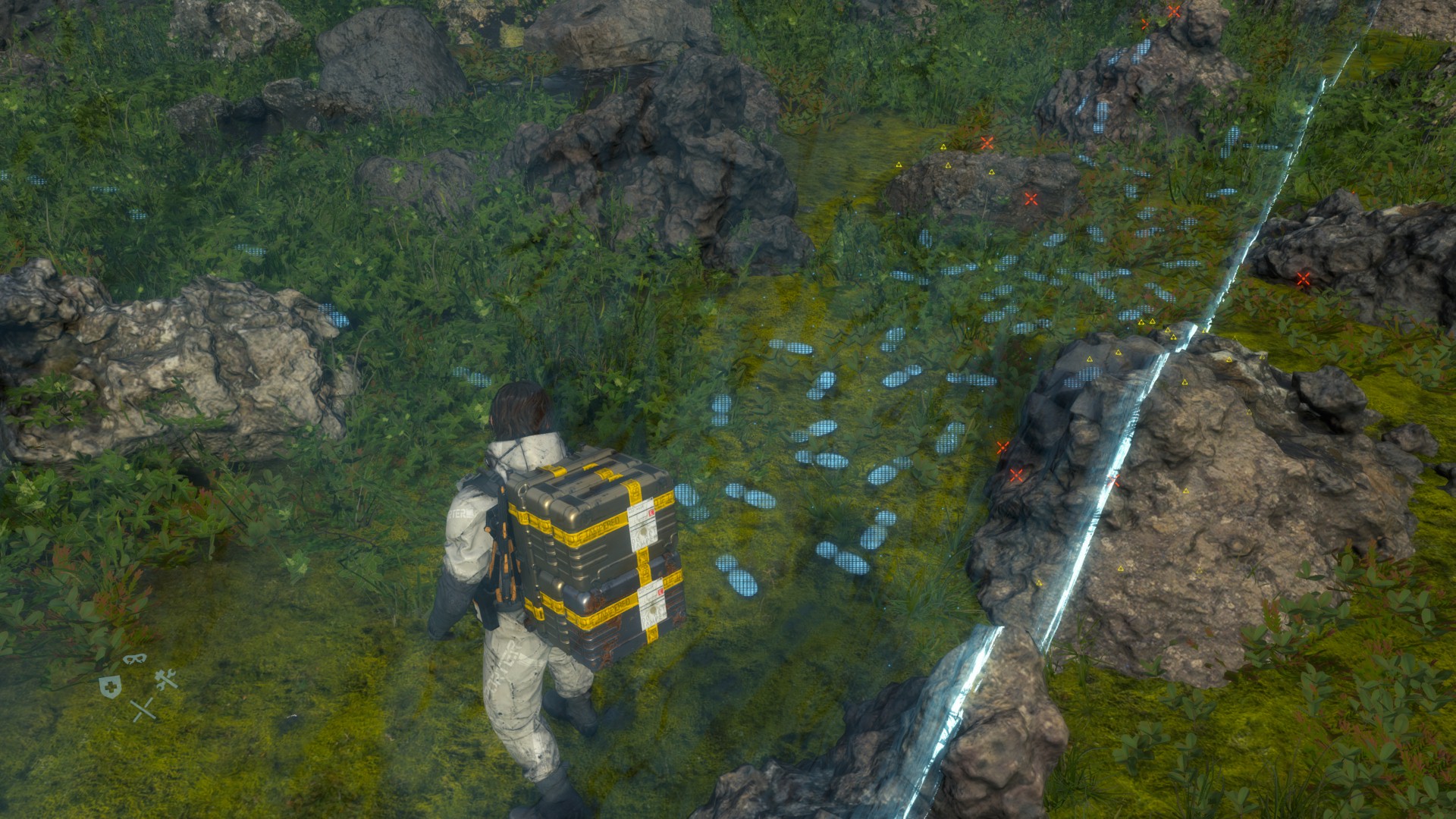
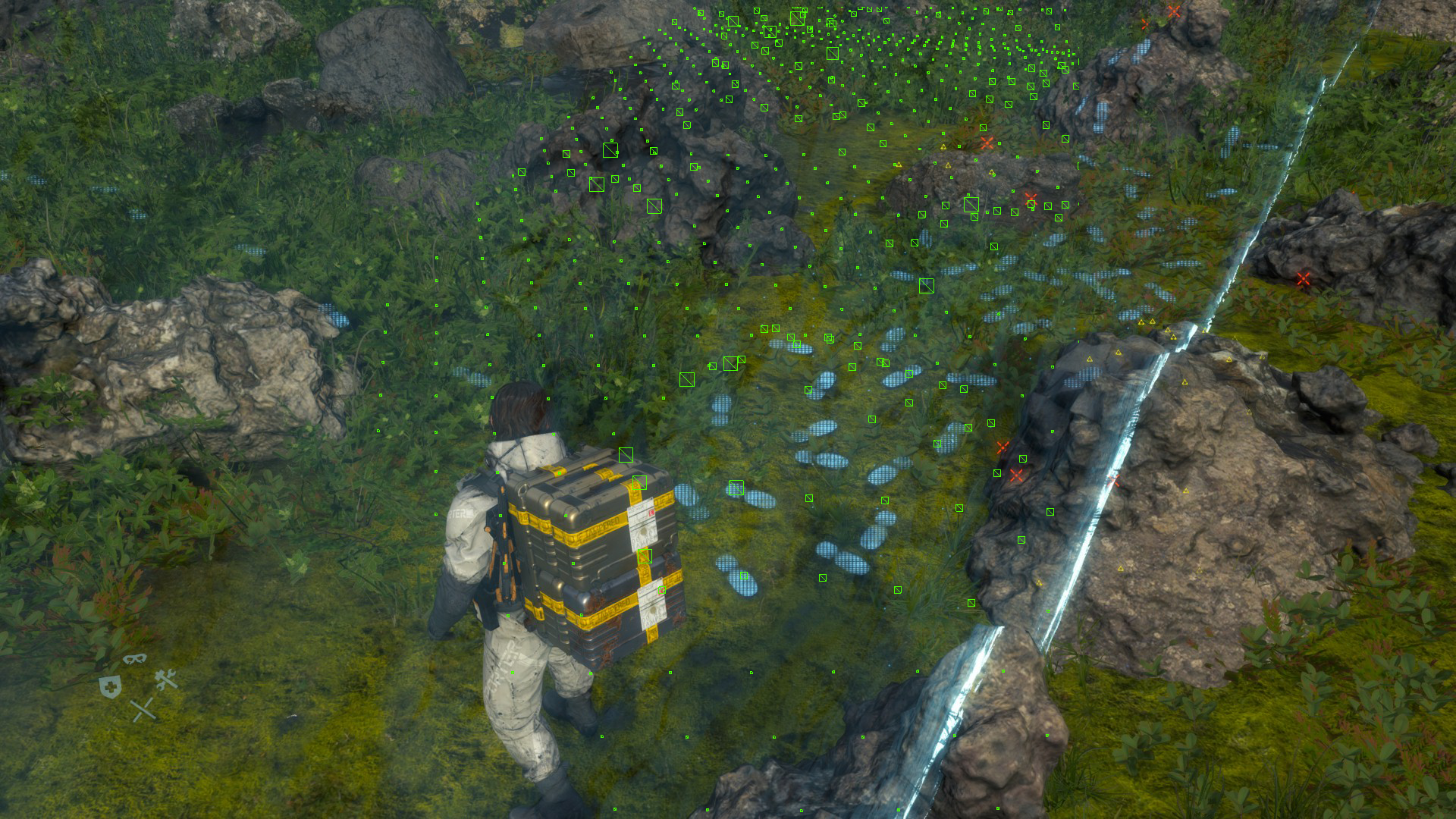
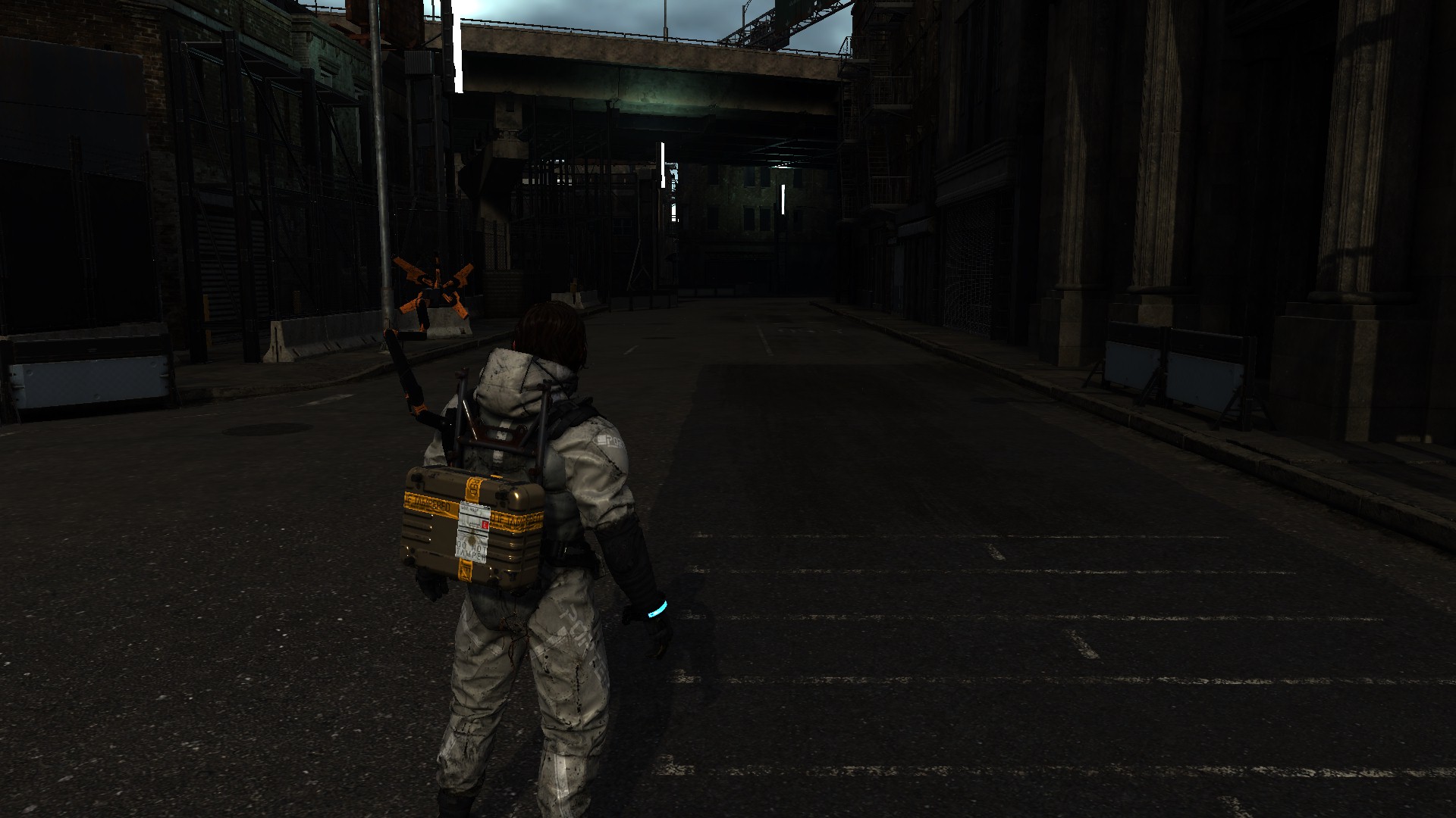
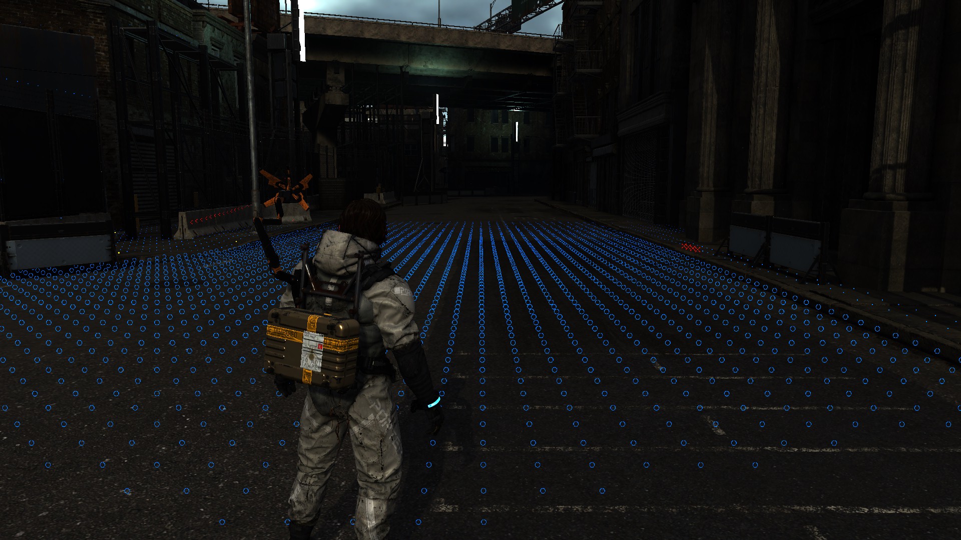
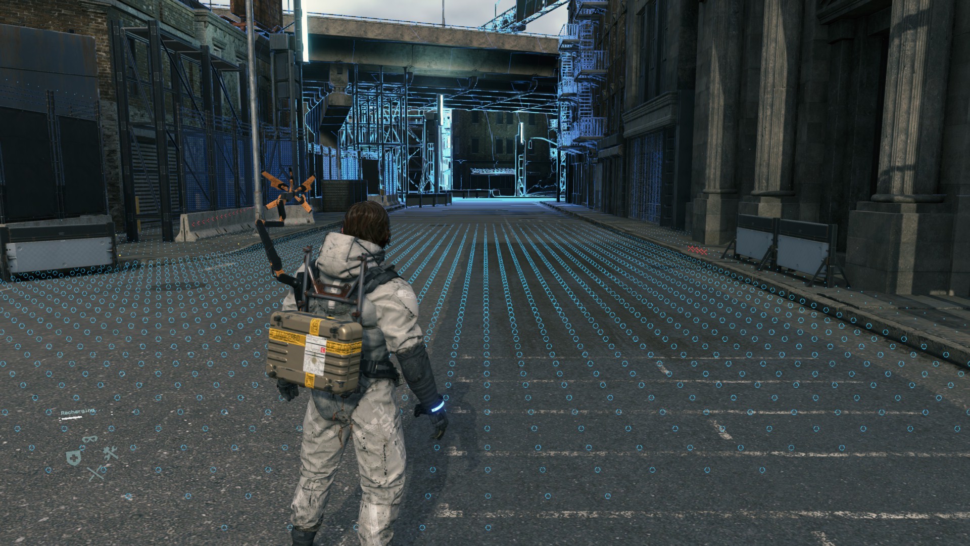

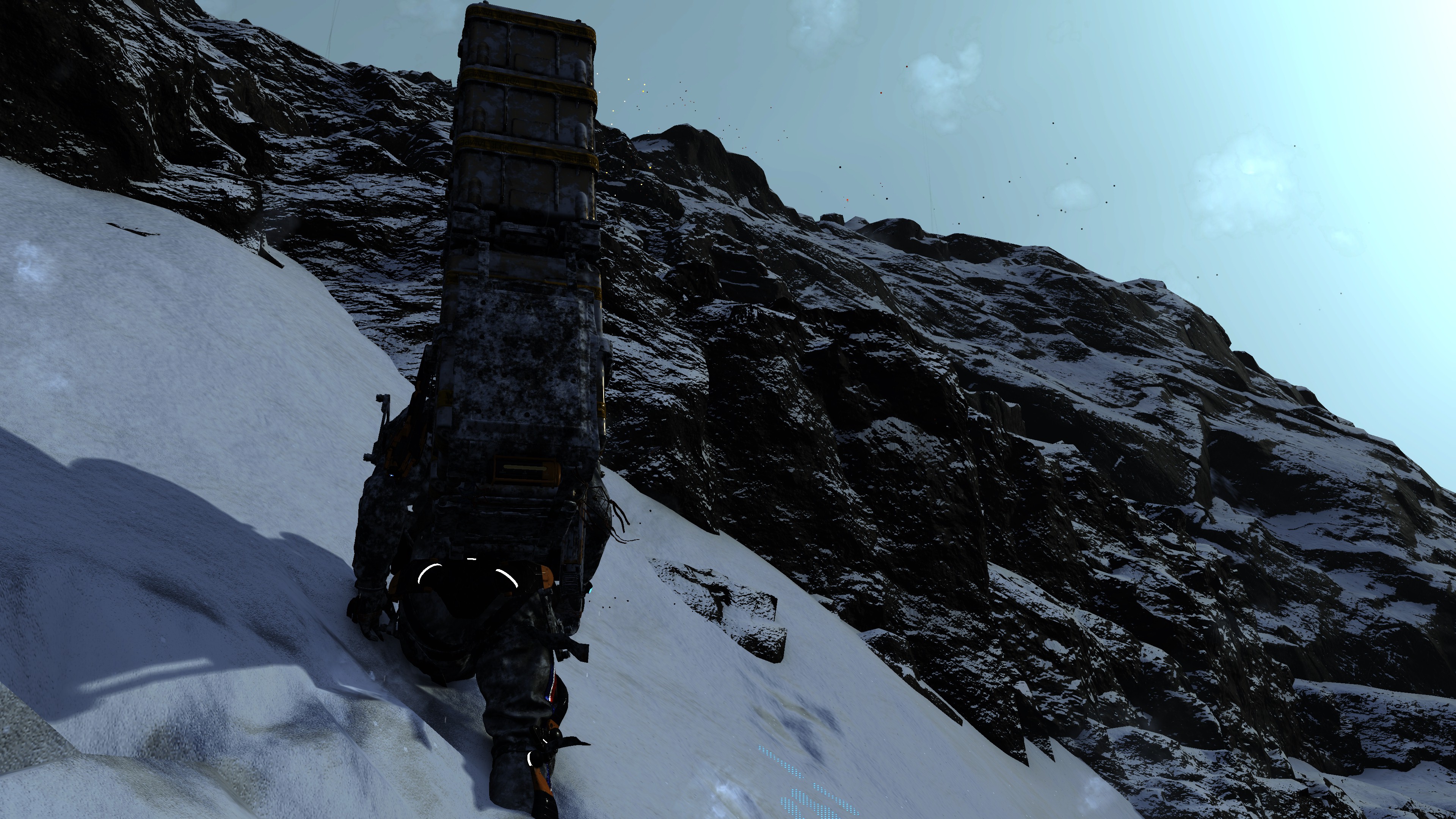

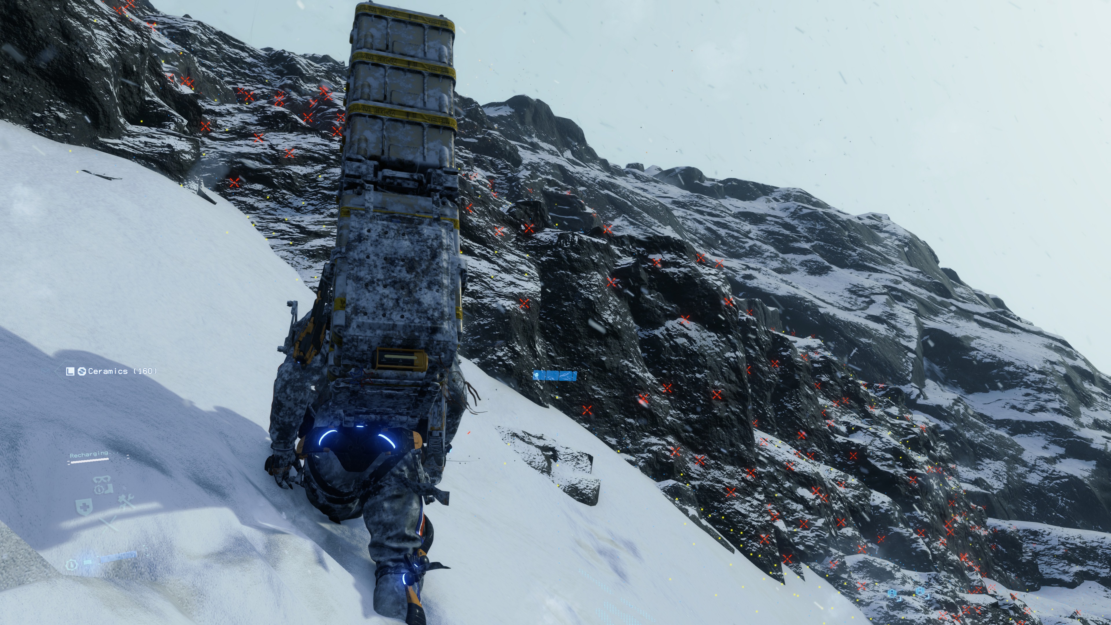
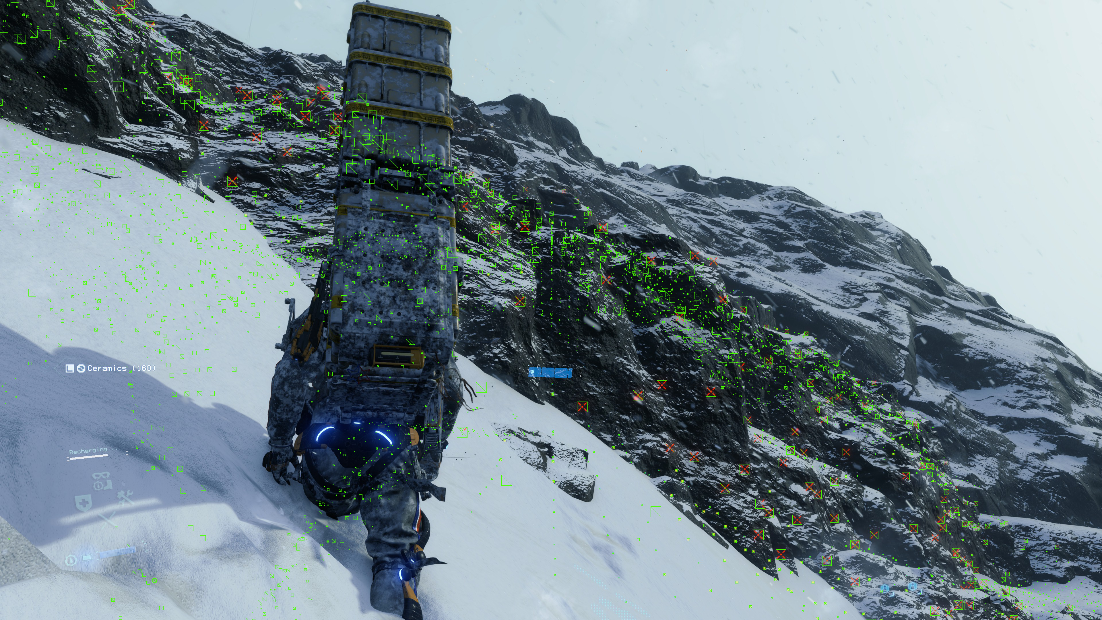
Because there is always more than what you can see or identity…a lot more!
Using a simple 96*96 atlas of markers, the markers get drawn through a DrawInstanced cmd at once, which is great & expected.


2.Particle Systems (Effects)
Once markers are all good, then comes the turn to the particle systems and effects, all the fancy stuff, from rain to debris to snow & whatnot. Where Particle Systems & the earlier Markers have things in common such as being instanced or being early simulated on compute, but there are a lot of differences between particle systems and the Markers, that:
1. Particle Systems are a full renderpass, where Markers are always a single command.
2. Particles Systems get their value simulated in the compute and values differ every frame, where Markers have some sort of “static” values out of the compute.
3. Particle Systems use multiple resources, that differ per particle system. Where Markers have almost a single resource for them all
4. Particle Systems’ pixels get shaded usually as deferred pixels, which means they consider Aleph, Cubemaps, BRDF,…etc., Where Markers don’t do that, and they mostly just get a solid color.
Anyways, Once the renderpass for particles starts, it get into drawing patches of instances one by one, system by system until the end.
In the examples below, you will notice that the length of the particles rendering pass is not always the same. It depends on the frame complexity and the amount of the “different” particle systems exist in the frame. For example, the snow frame (the last one) is the most complicated one of the 3 examples.

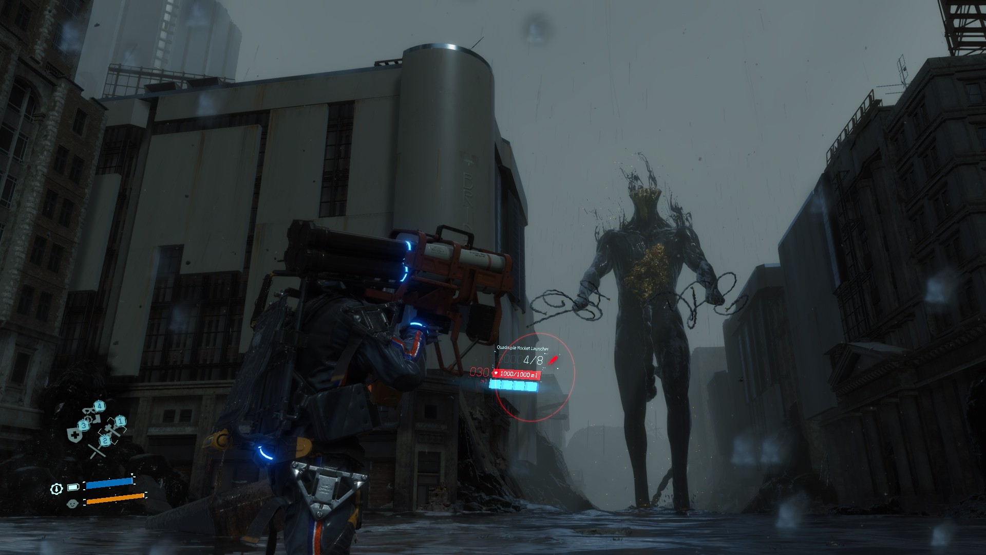


And if you ever wondering about that very thin lines that gets drawn as particles, those are basically just strands that you can find usually around Sam’s body as well as the cargo, if you bare closer look (such as the video below) you can see them easily around the Elbows & Shoulders…And sometimes just mid-air!
And for even clearer idea or closer look at those, i put this version below, where all the strands particles of the frame are highlighted in blue, zoom & compare both images, it is really settle effect most of the time, but it is taking most of the time of the particles drawing renderpass.
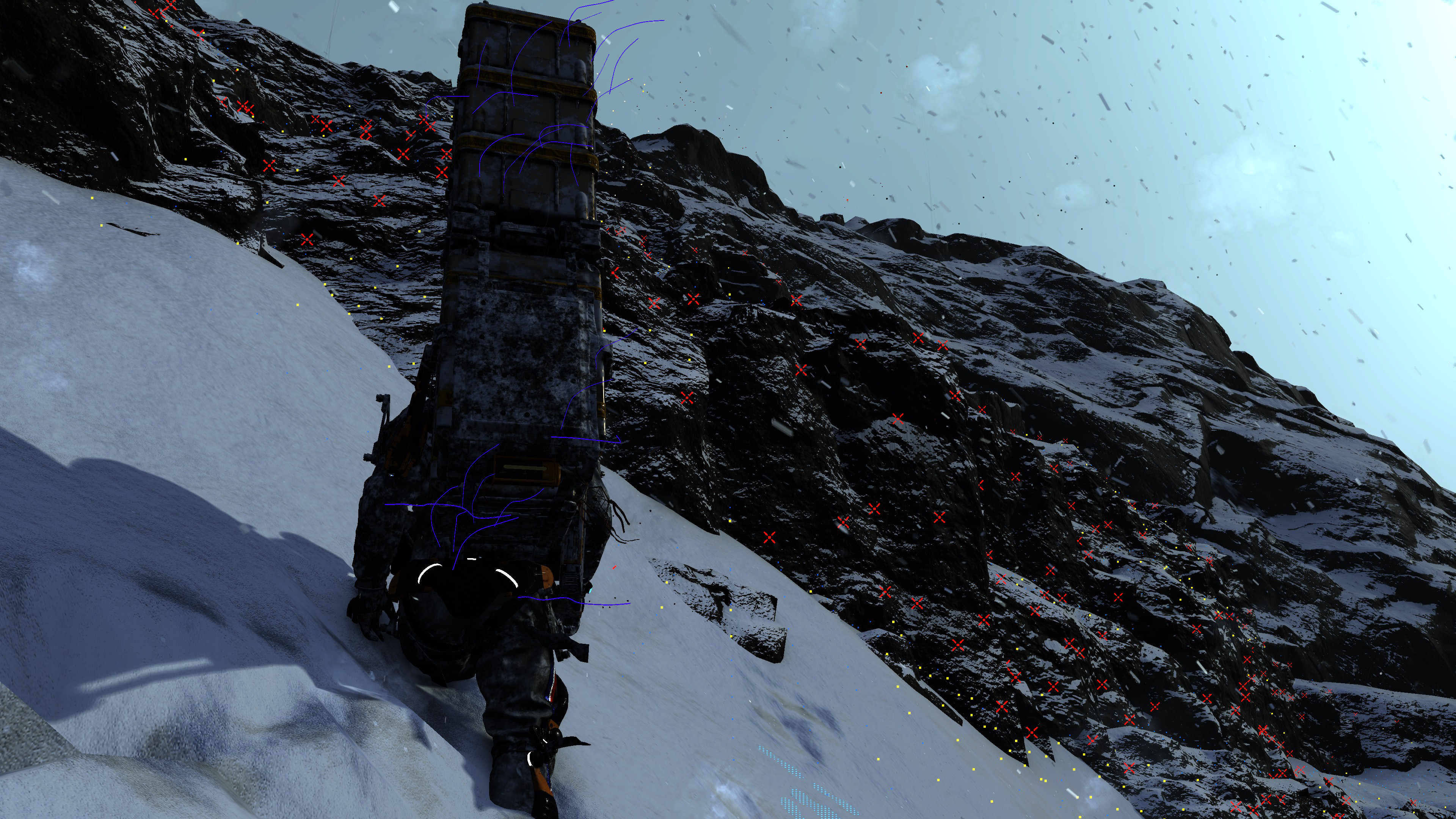


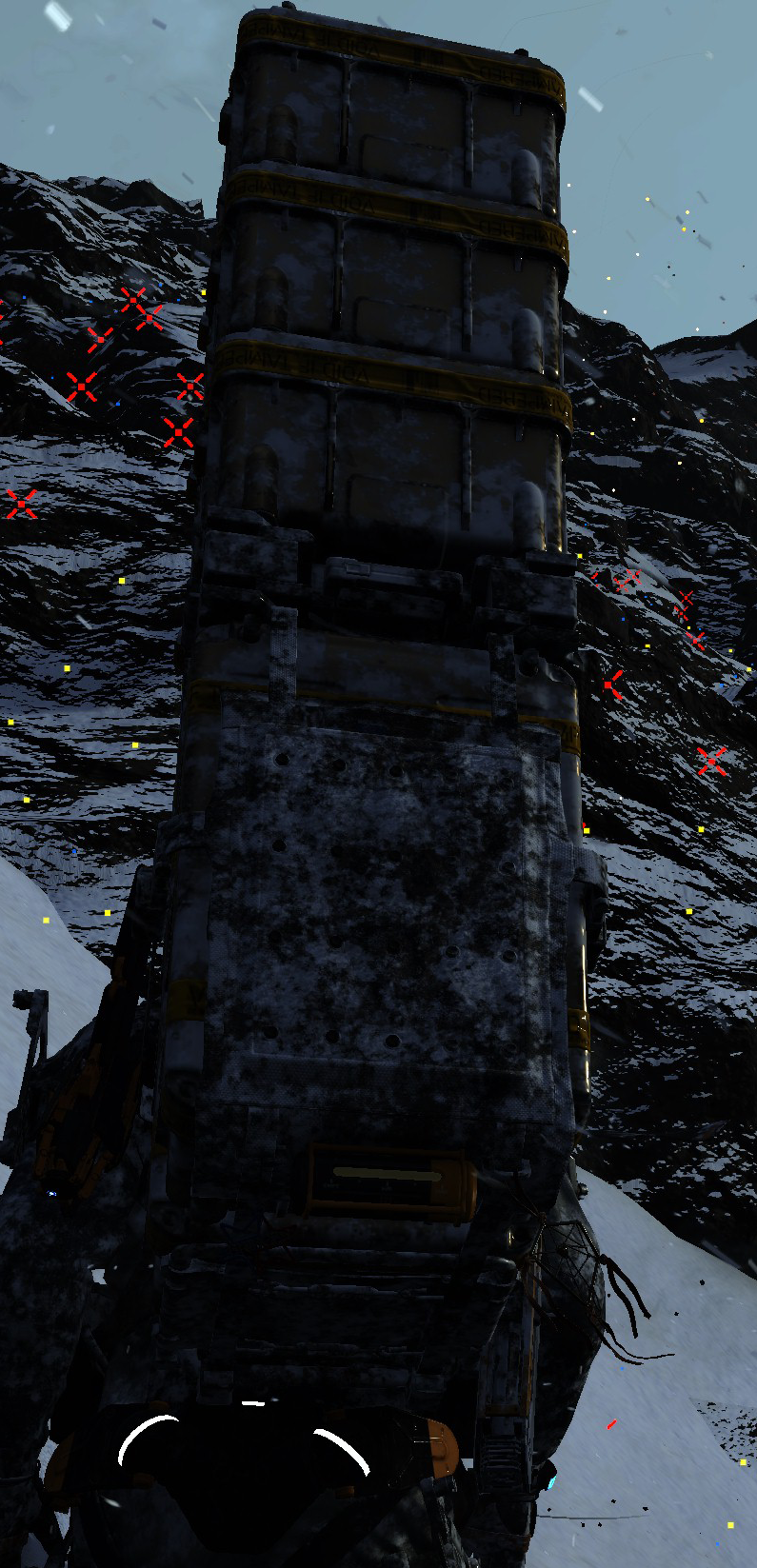
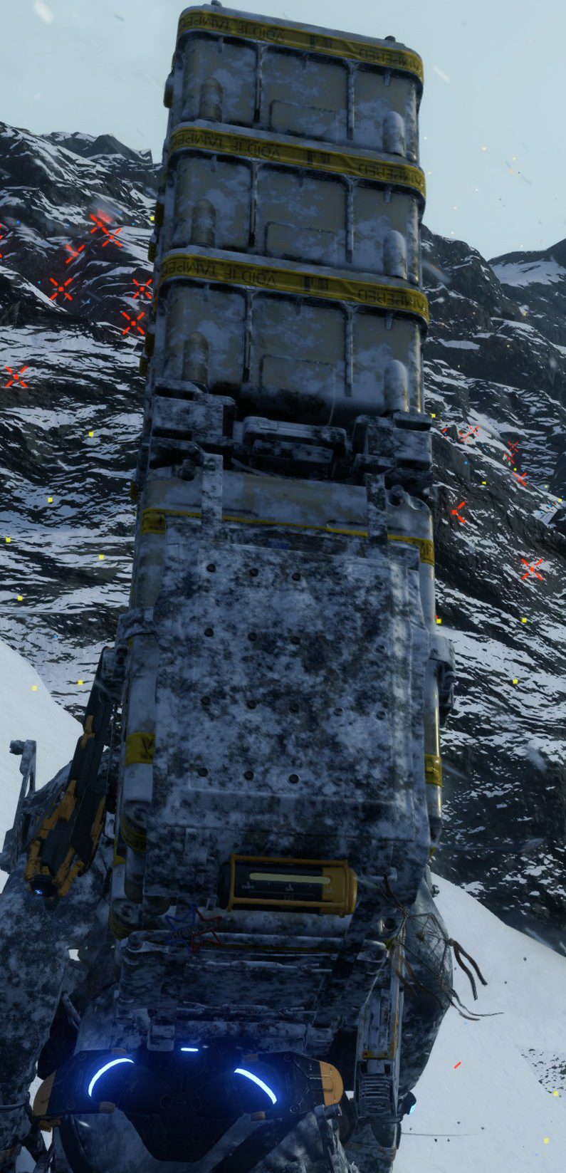
Anyways, for the purpose of drawing the GPU particles, there are quite a few parameters passed to the shader, including an array of entries that is applied “per instance”, so that array can get really fat!
Shader Instance Per Instance Constants
struct ShaderInstance_PerInstance_Constants
{
     struct StaticPerInstance_Constant
     {
	float minVariable0;
	float minVariable1;
	float minVariable2;
	float minVariable3;
     }

     struct ParticleVertexGenerationStaticParams
     {
	float4 mDistanceFadeRanges;
	float4[] mVertexAttrLookup0;
	float4[] mVertexAttrLookup1;
	float4[] mAspectRatioCurve;
	int4 mVertexAttrSources0;
	int4 mVertexAttrSources1;
	float mNormalBendFactor;
	float mAspectRatio;
	float mAspectRatioVariation;
	float mStretchFactor;
	float mMotionVectorScale;
	int mMeshSubdivisionCount;
	float mTrailTextureScaleU;
	int mFlags;
	int mStrideU;
	int mStrideV;
	float mSubTexAnimFrequency;
	int mSubTexAnimStartFrame;
	int mSubTexAnimAnimationSource;
	int mSubTexAnimSingleRowIndex;
	int mLightSamplingBufferWidth;
	int mLightSamplingBufferHeight;
	int mLightSamplingBlockSize;
	int mLightSamplingSampleSize;
	int mParticleShape;
	int mPadding0;
     }

     struct ParticleVertexGenerationDynamicParams
     {
	float4x4 mParticleSystemWorldMatrix;
	float4x4 mParticleSystemPrevWorldMatrix;
	int mParticleDataStartIndex;
	int mParticleCount;
	int mTotalParticleSpawnCount;
	int mLightSamplingBlockStartIndex;
	float mFrameTime;
	float mEffectTime;
	int mDynamicParamsPadding1;
	int mDynamicParamsPadding2;
     }
}
This is the structure members and sub-members, imagine several entries of that same struct per instance, with a (what seem to be) maximum of ~75 entries. So you can tell, in theory, the game can’t have more than ~75 particle systems/emitters in one frame…
Some times (or to be exact some particle systems) would utilize a punch of 3d textures (previous compute data/UAVs) that represents the data for Force Fields or Volumetric Light Volume, in order to do proper shading.


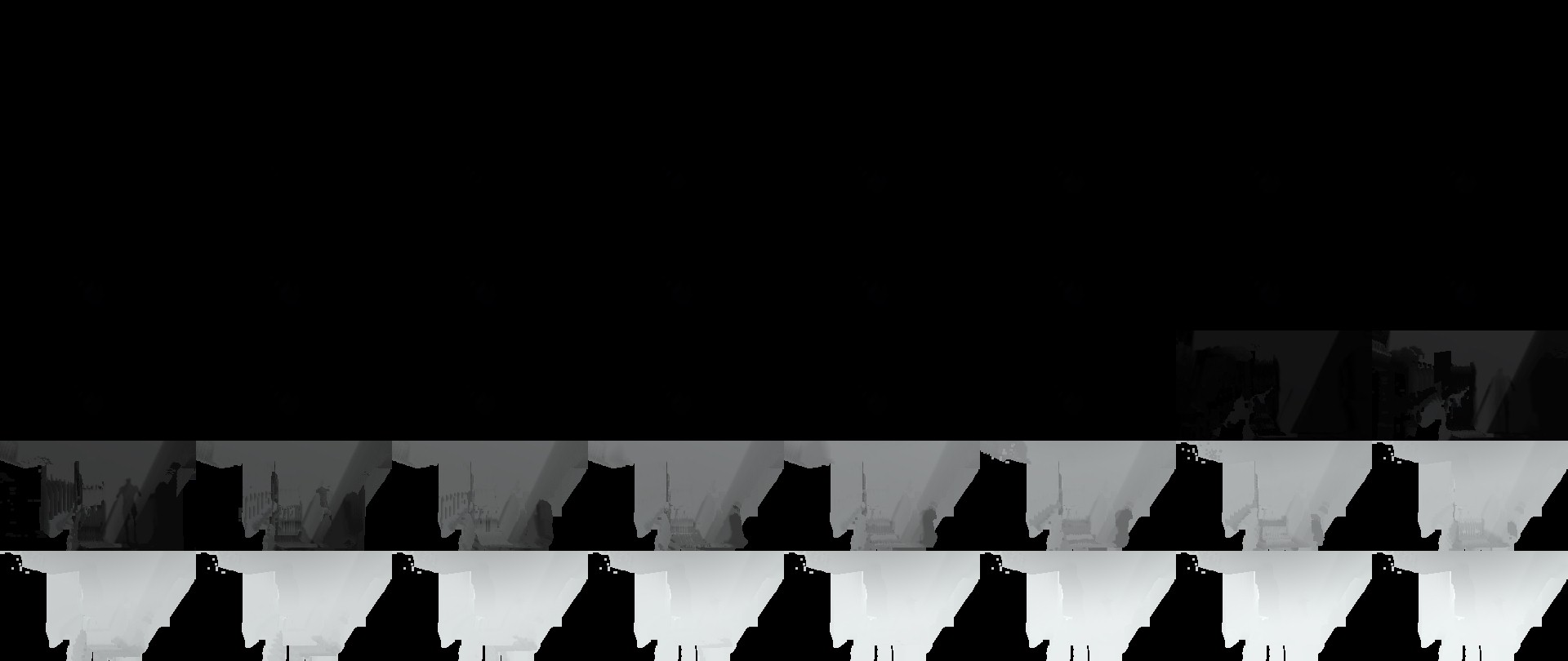
Example 2


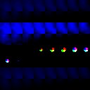

Example 3


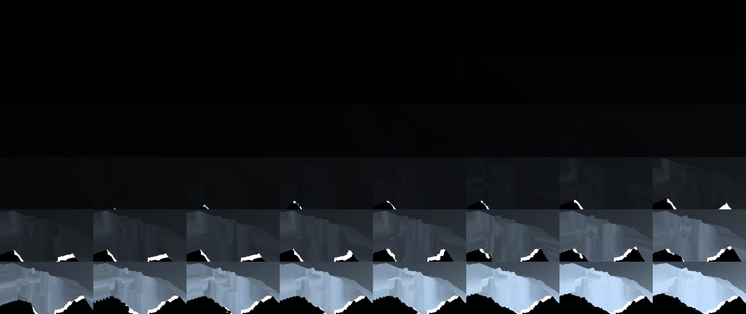
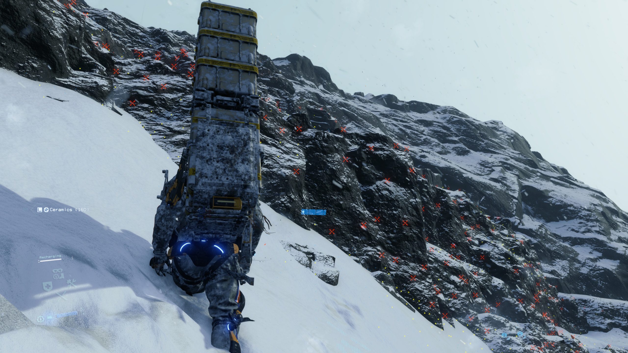
And of course, eventually particles are not only drawing to the final lit rendertarget, but also drawing to the lovely old friend Depth Blend buffer
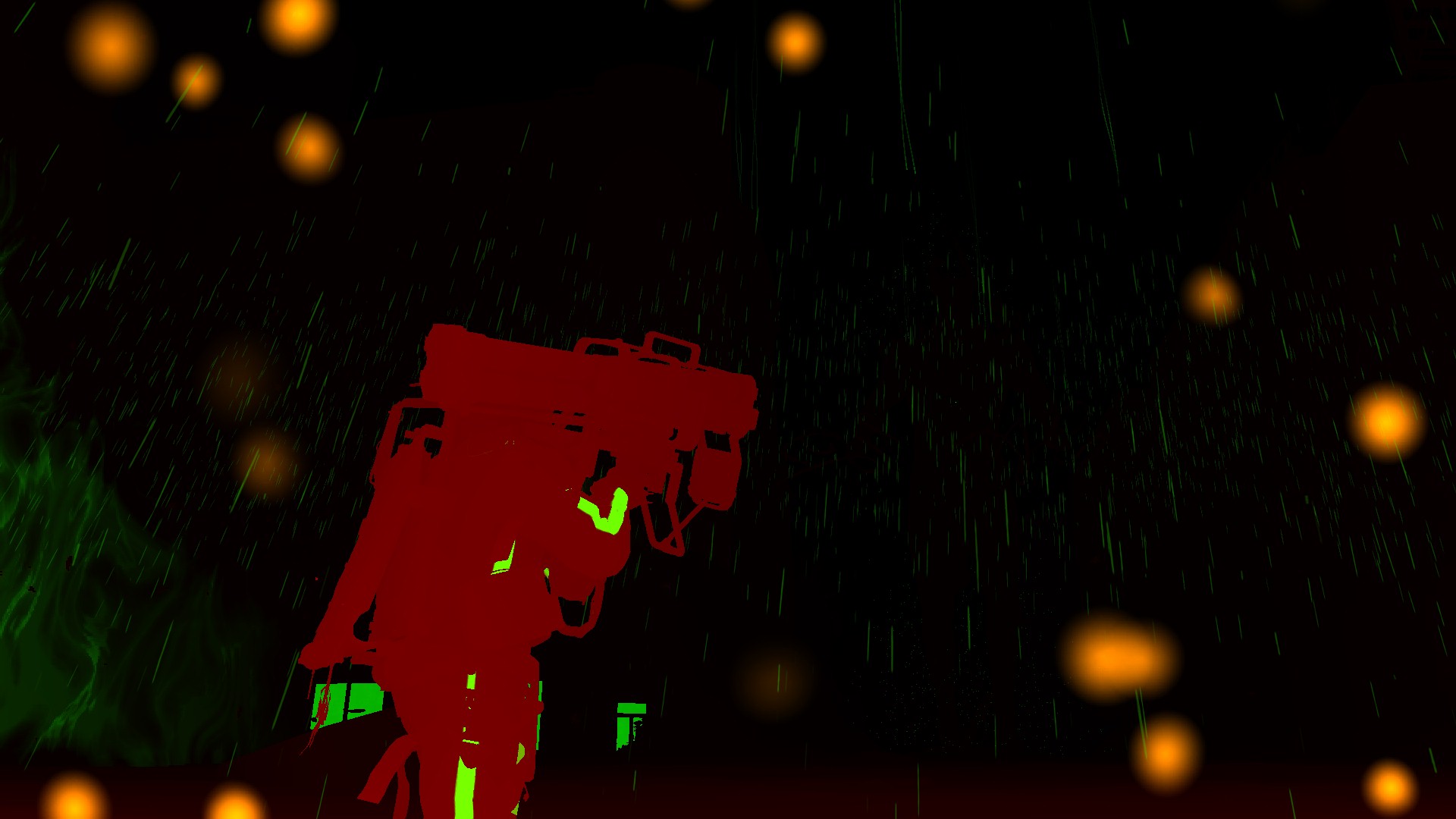
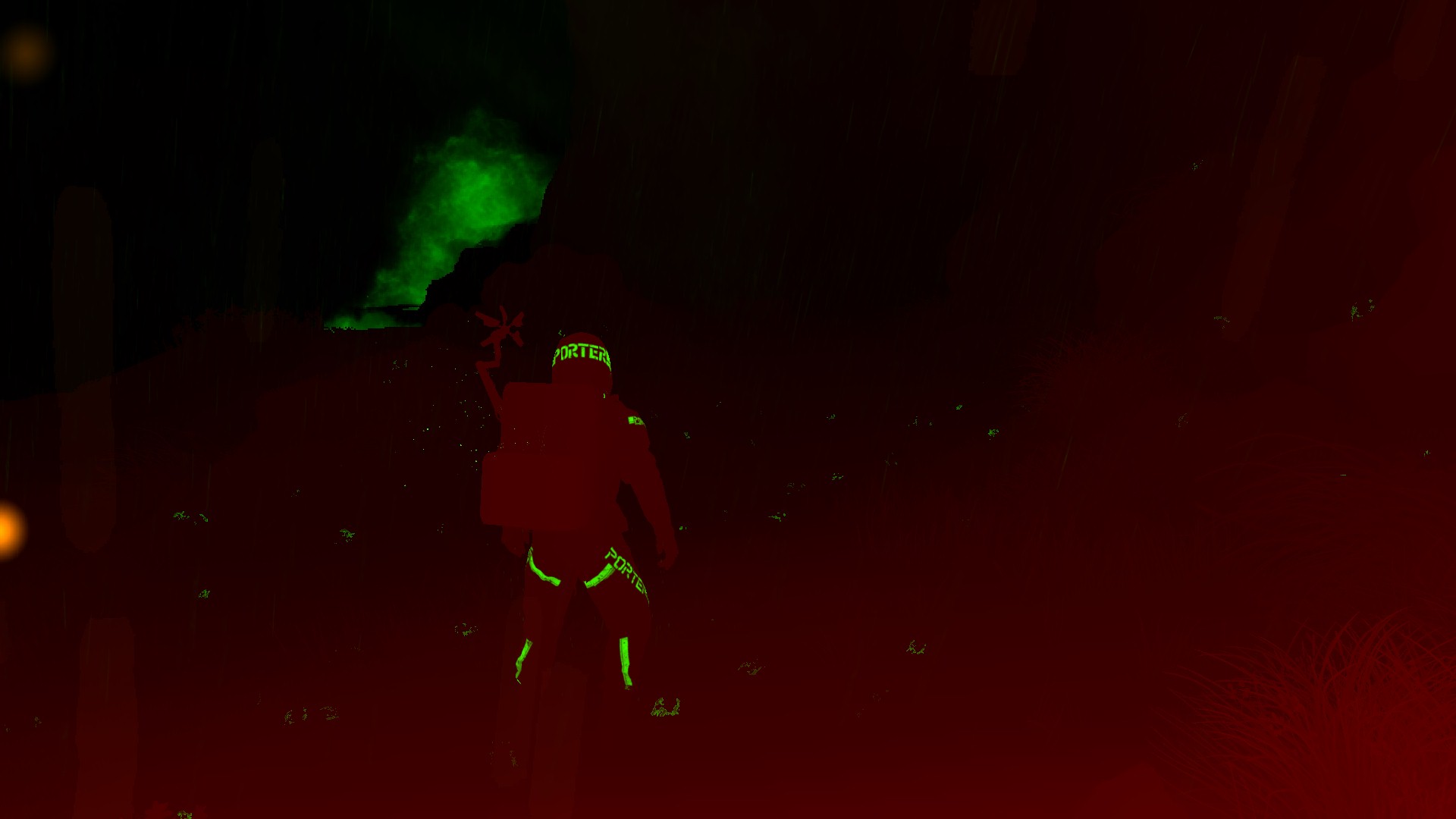
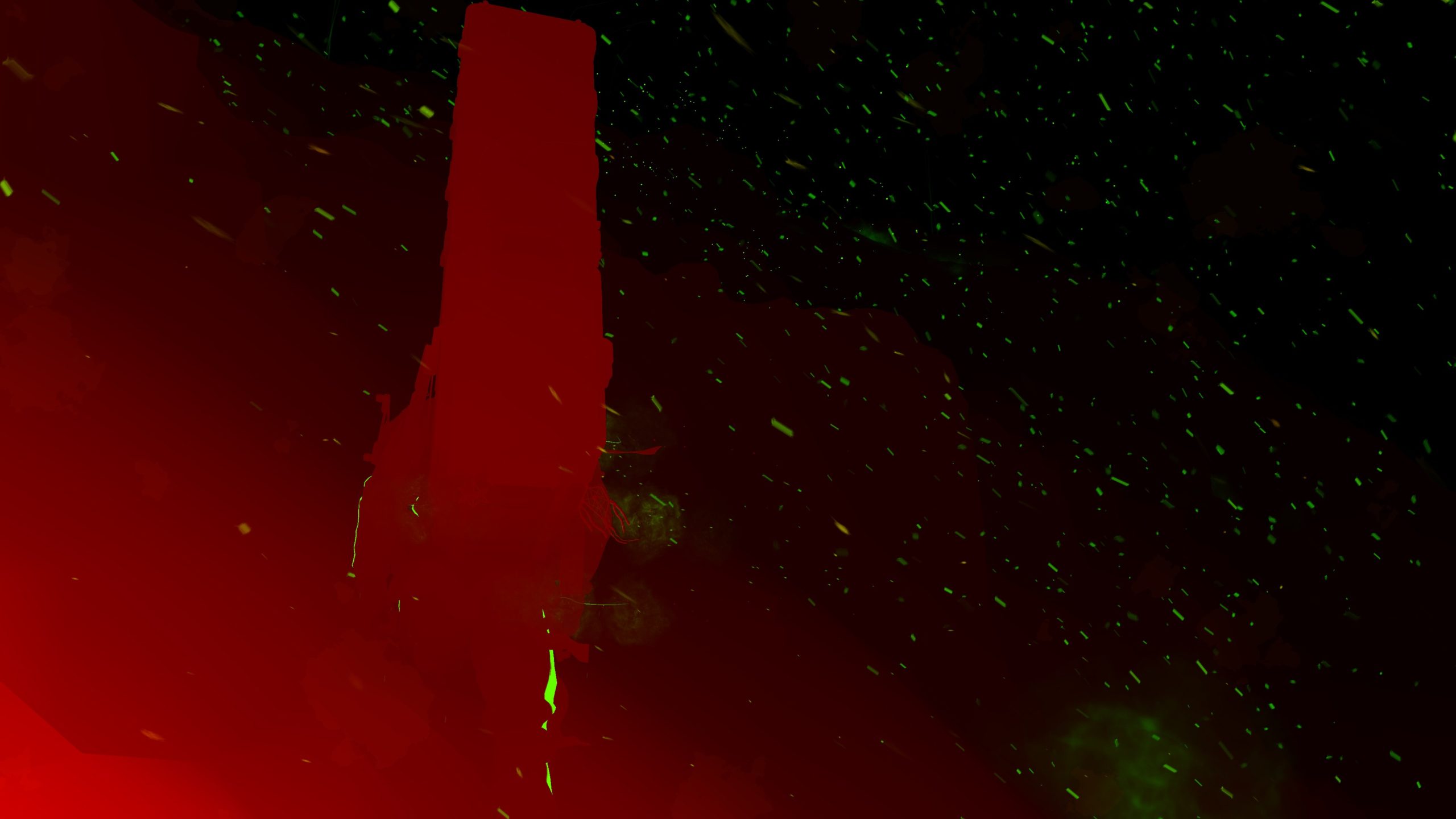
Downscale Scene Texture
Nothing very fancy, but just doing a scale down by 1/2 for the current scene texture as it is, as it will be needed just in few seconds as a base for the Motion Blur Texture.
During this humble stage, there is a new rendertarget generated next to the 1/2 scene texture, it is called Scene Luminance Texture which is a 1/2 res as well, you can think about it as if it is a single channel desatruration of the current scene texture but in a different color format (range). This one is needed very soon during Bloom Post-Processing, exactly during the preparation for the Bloom itself, when creating what so called the “Bloom Scene Source“


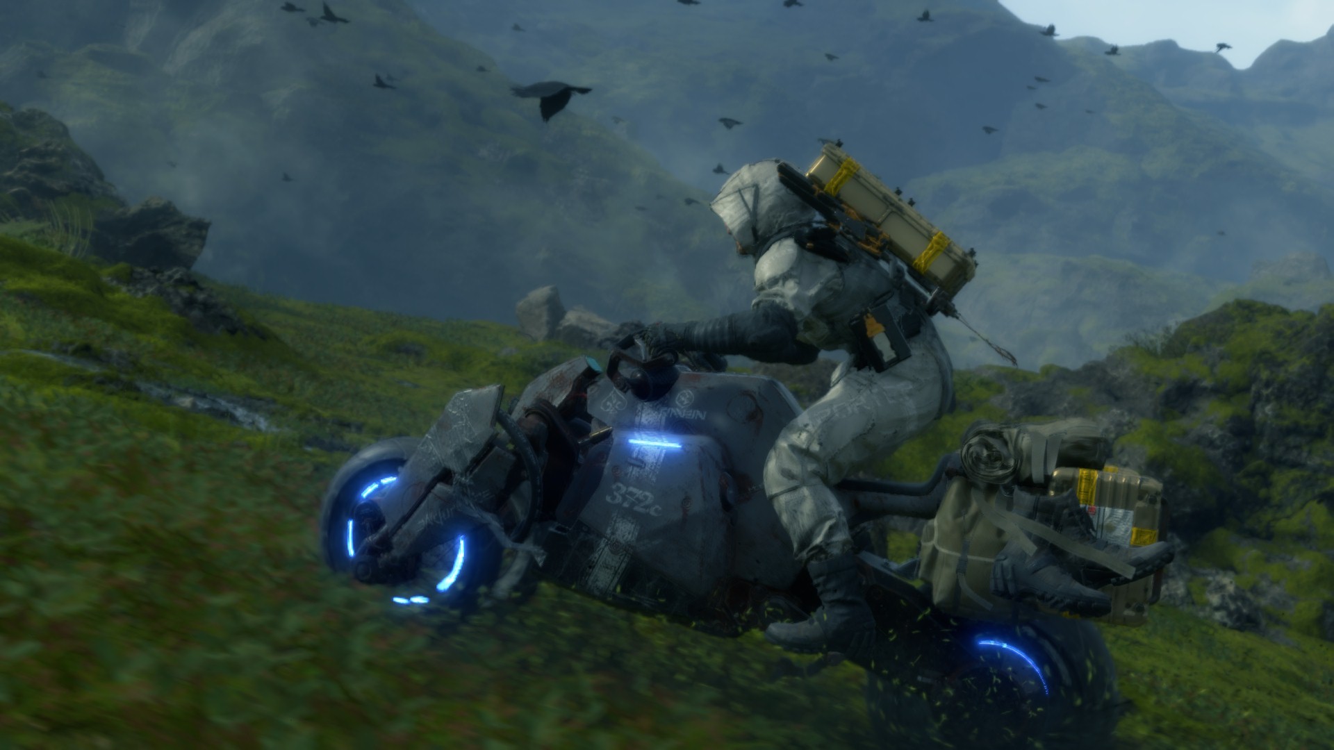
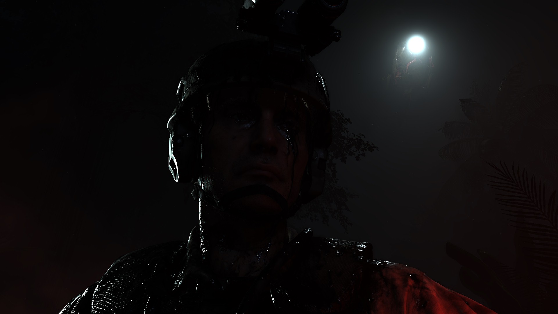

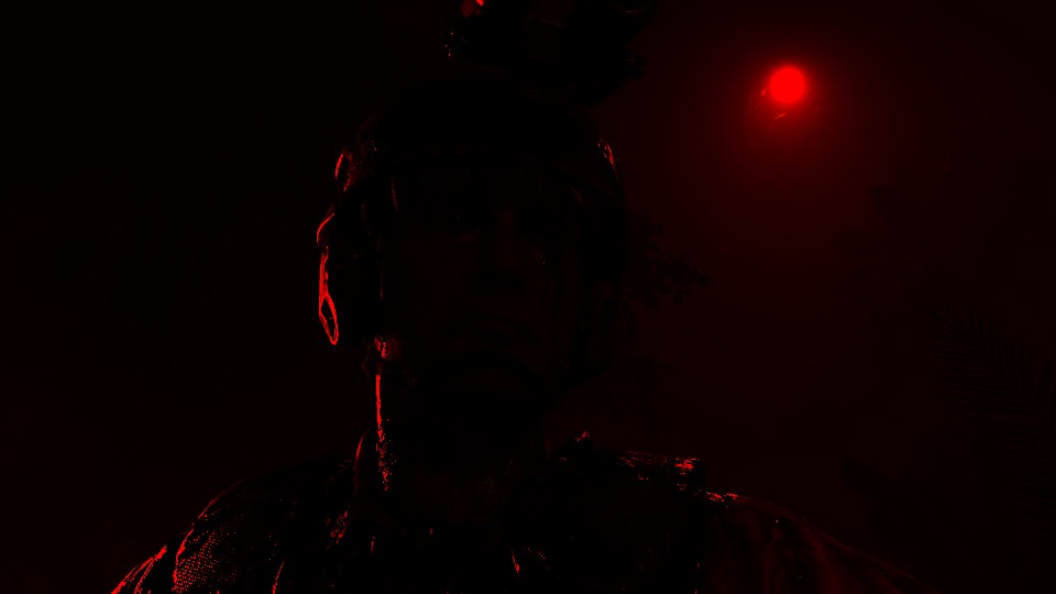


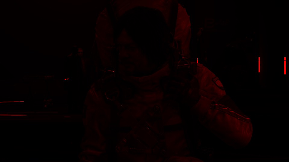


the 3rd image is “Just for demonstration”, i put the color range for something more readable, but the actual Scene Luminance rendertarget is the darker one
Motion Blur
The motion blur takes place in few distinctive steps, starts by preparing the current Motion Vector Texture, then generating the Motion Blur Texture itself (rendertarget), and finally apply the Motion Blur effect.
1.Motion Vector Texture Prepare
While the Motion Vector texture been created few steps ago, now it comes the time to prepare it to be actually used. This is done by:
1. Changing it’s format from RG16_FLOAT to RGBA8_UNORM.
2. Reduce the size by 1/2, and of course it is already 1/2, so this mean finally a 1/4 of the target swapchain (480*270 when target 1080p, or 960*540 when targeting 4K,….etc.)
3. Radial Blurring the Motion Vector Texture 4 times (Horizontally, Vertically, Horizontally, Vertically)
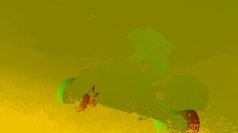
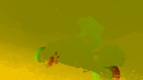


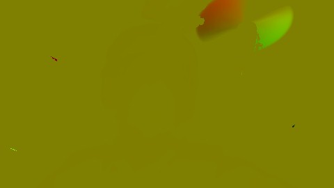


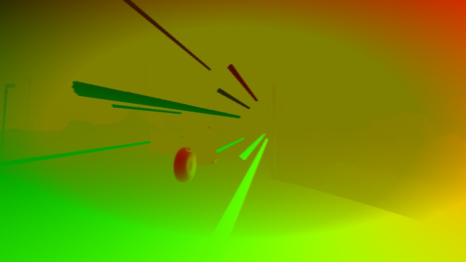


And for that purpose, some of the following params are passed to the fragment shader.
Radial Blur Params
struct mInUniform_Constant
{
     float4 mRadialBlurPosRadius;
     float4 mRadialBlurScale;
     float4 mMaxMotionDisplacement;
     float4 mMotionVectorScaleCenter;
     float4 mMotionVectorScaleCoeff;
     float2 mAspectRatioCompensation;
}
Radial Blur Params 2
struct mInUniform_Constant
{
     float4[4] mKernel;
     float4 mPostProcessUvRange;
}

/*
//Blur 1
mKernel[0] -0.00223, 0.00, 0.10938, 0.21875
mKernel[1] -0.00063, 0.00, 0.39063, 0.39063
mKernel[2] 0.00063, 0.00, 0.39063, 0.39063
mKernel[3] 0.00223, 0.00, 0.10938, 0.21875

//Blur 2
mKernel[0] 0.00, -0.00397, 0.10938, 0.21875
mKernel[1] 0.00, -0.00111, 0.39063, 0.39063
mKernel[2] 0.00, 0.00111, 0.39063, 0.39063
mKernel[3] 0.00, 0.00397, 0.10938, 0.21875

//Blur 3
mKernel[0] -0.00223, 0.00, 0.10938, 0.21875
mKernel[1] -0.00063, 0.00, 0.39063, 0.39063
mKernel[2] 0.00063, 0.00, 0.39063, 0.39063
mKernel[3] 0.00223, 0.00, 0.10938, 0.21875

//Blur 4
mKernel[0] 0.00, -0.00397, 0.10938, 0.21875
mKernel[1] 0.00, -0.00111, 0.39063, 0.39063
mKernel[2] 0.00, 0.00111, 0.39063, 0.39063
mKernel[3] 0.00, 0.00397, 0.10938, 0.21875

*/
i put the mKernel values for all the array entries per Blur step of the Radial Blur, just for clarity…
2.Motion Blur Texture Create
Using the current Scene Texture at it’s current state in addition to the Motion Vector Texture after it’s preparation, the game will spit out the Motion Blur Texture.
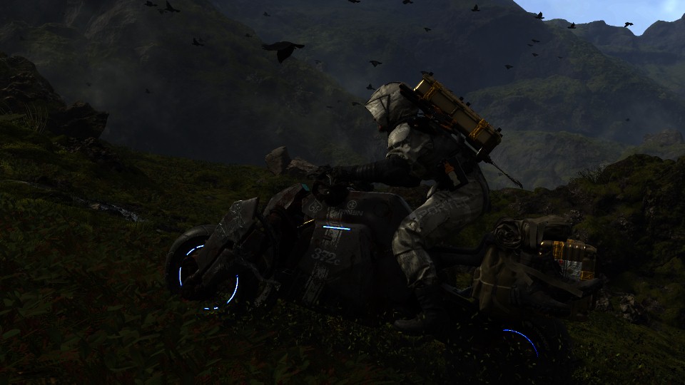

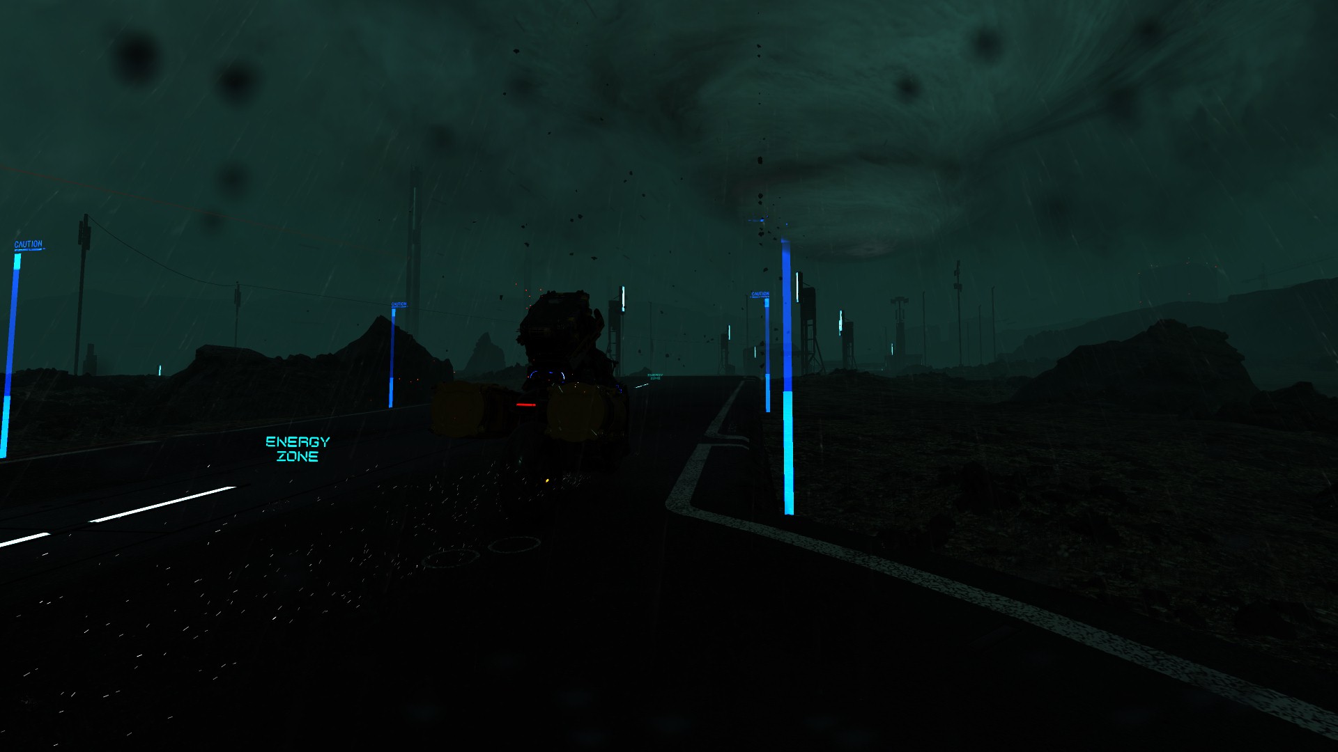
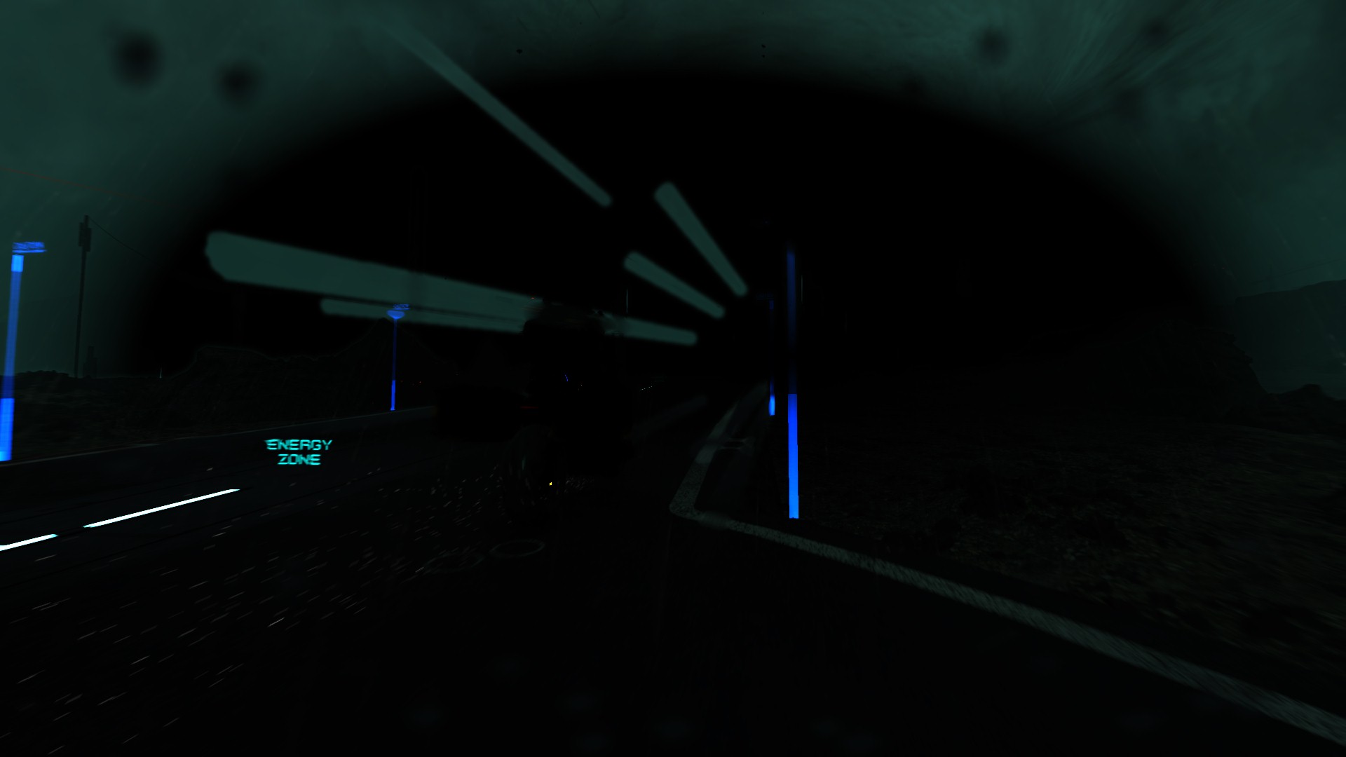
very very settle movements…You can’t go wrong with a Reverse trike
Motion Blur Params
struct mInUniform_Constant
{
     float4 mPostProcessUvRange;
     float mPostProcessBokeValue;
}
3.Motion Blur Apply
And finally apply the Motion Blur Texture to the Scene…


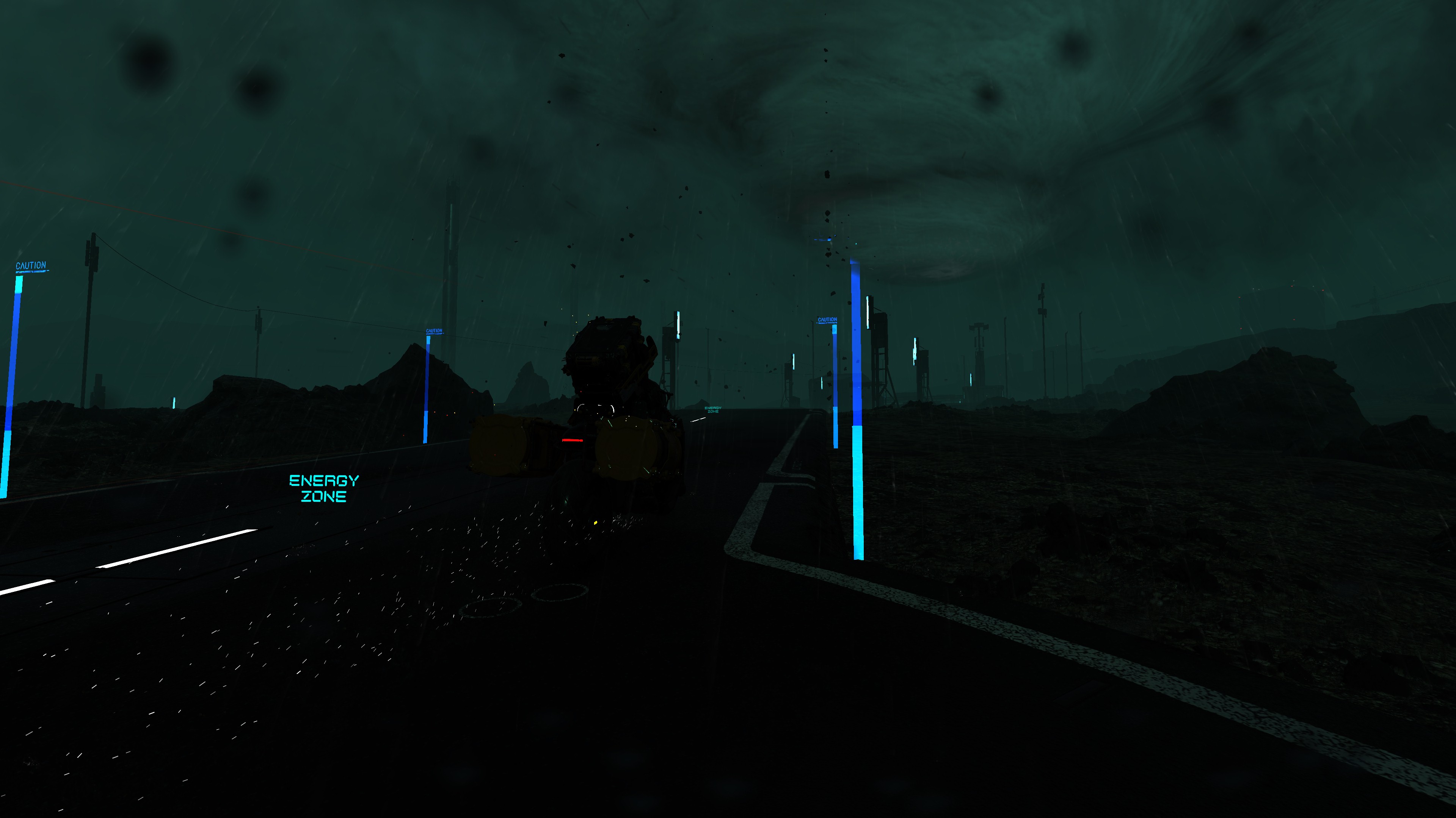

4.Clear
By the end of this step, a Clear called for the Motion Blur Texture rendertarget, so it can get reused later in something else…
DOF’s CoC Prepare [Not Always]
As mentioned earlier that DOF is absent in the game during gameplay (which is normal, and this is the case at ~80% of games), and while this step is only about preparing the CoC texture for a later use with DOF application by the end of the frame, this step is totally absent altogether from any gameplay frames. So, consider this step a Cinematic only step.
This happens in few distinctive steps
1. Generate CoC Texture
Using the Depth, Depth Blend and Motion Vectors, can generate the CoC texture in full resolution


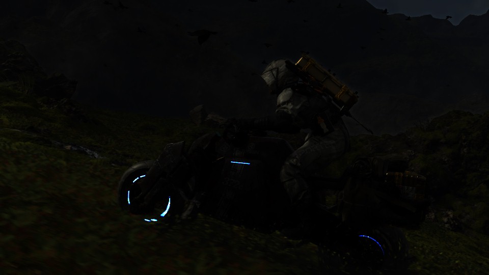

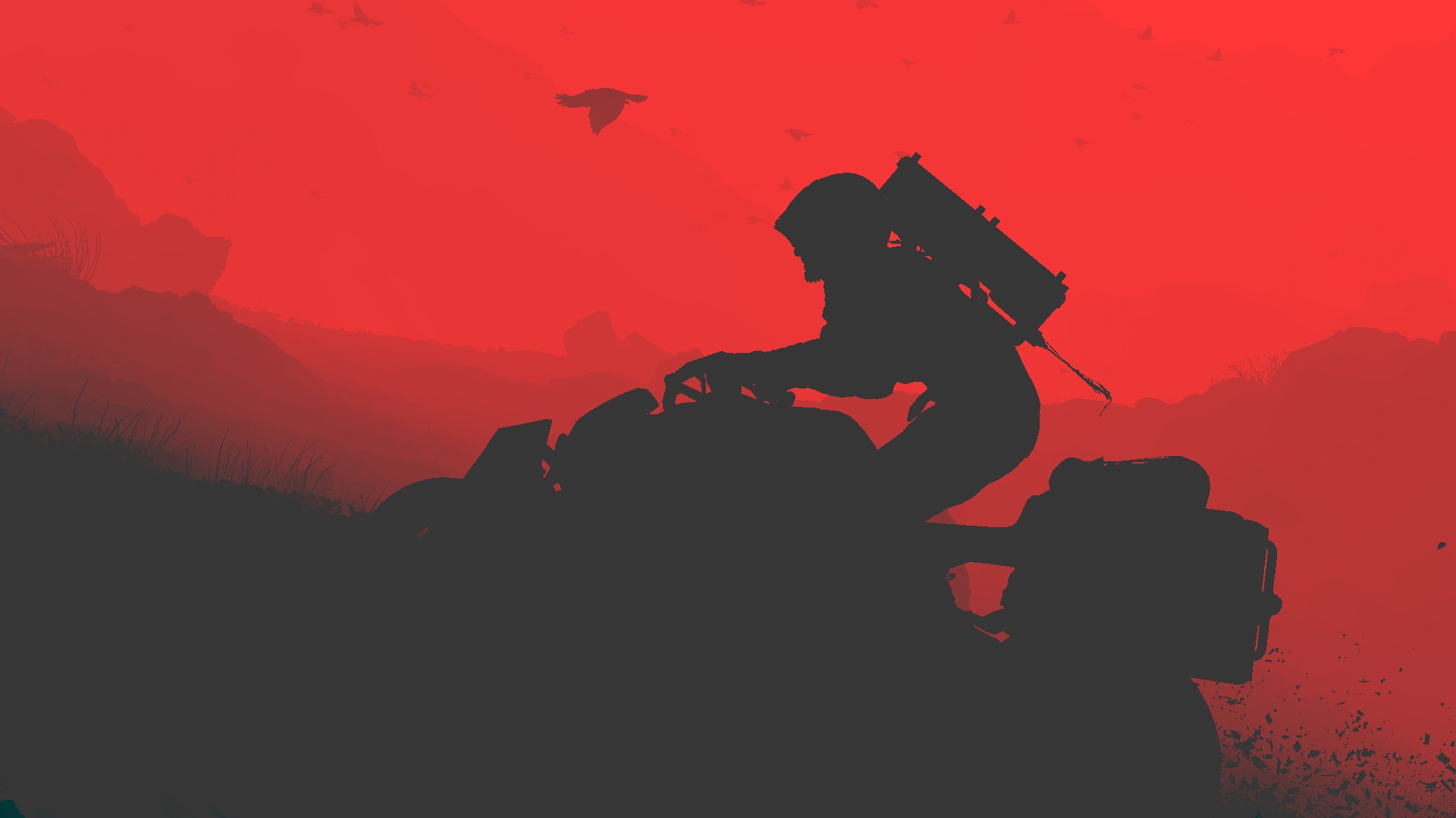
2. Generate Min/Max CoC Texture
Then it’s a sequence of CoC downscaling in order to end up with the Min/Max CoC texture that will be used shortly to apply DOF. And basically in each step, it consumes the output of the previous step.
Step 1:
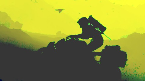
Step 2:

Step 3:

During those downscaling, the shader utilizes Point Sampler, with Clamp to Edge addressing mode.
Now you might be asking, what or how downsampling happens in the last step, because the input texture is 120*68 and the output texture is 120*68 as well?! Where it made perfect sense earlier when downsample from 480*270 to 120*68. The answer is, in that last step the downsample is not happening at the texture level, we don’t blit the image or so. The actual surface/view is what get downscaled and stretched to “fit” the existing texture size. the view target size is set to (119 * 67) which makes sense where viewport starts at 0 not 1.Now the question is, why not unifying the method, it doesn’t matter (or it does ( ͡° ͜ʖ ͡°)) which one, a texture level or a view level, why not having it consistent across all steps?…i’m just curious…
3. Clear
By the end of this step, a Clear called for the CoC Texture rendertarget, so it can get reused later in something else…
Now with all steps done, putting it all together in couple more examples (just to match with the DOF examples below)


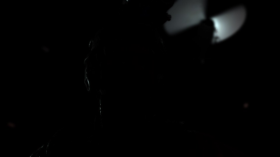


And one more…
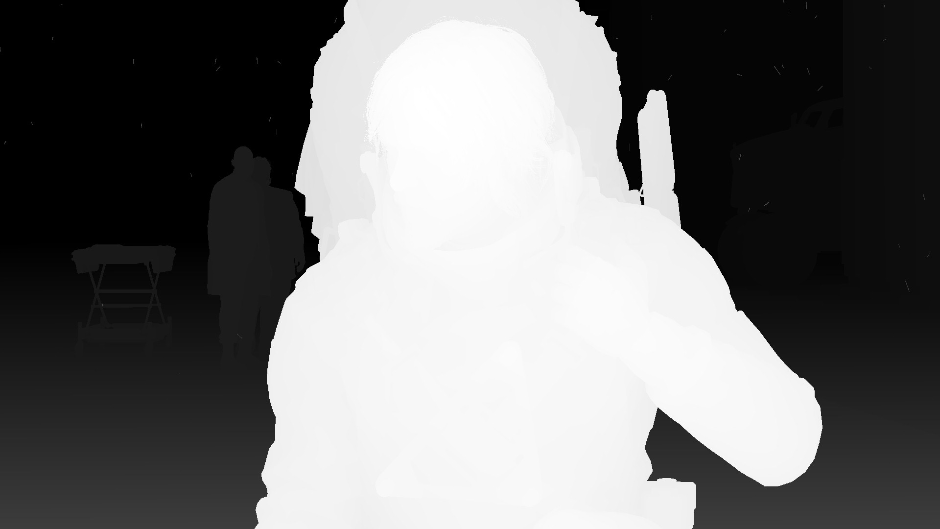
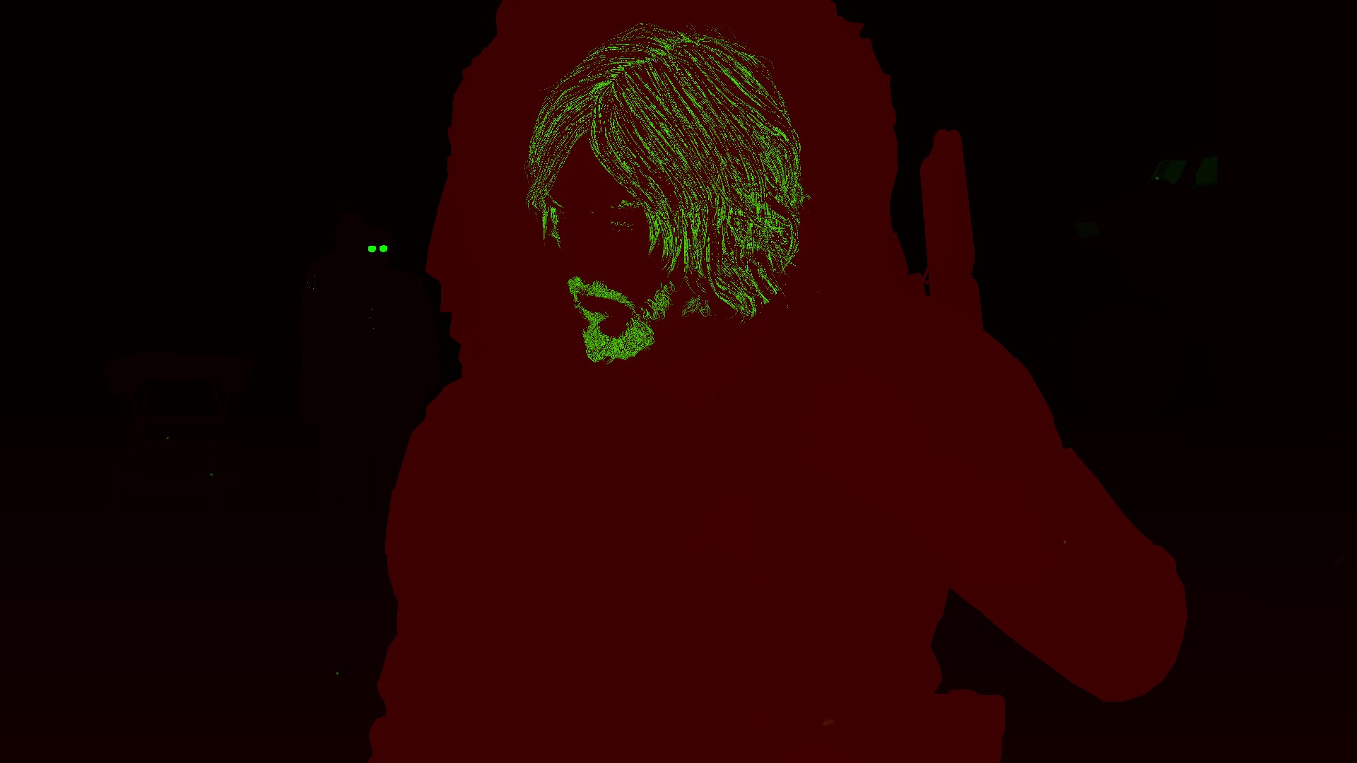


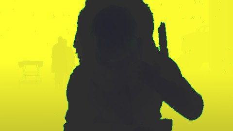


Something to keep in mind here, the fact that 1st Min/Max is 480*270 means that this 1st Min/Max is 1/4 of the target resolution (1920*1080). But does this mean the 2nd and 3rd Min/Max which is 120*68 is 1/16 of the target resolution?
Well, the answer is Yes and No. Yes it is 1/16 of the resolution (1920/16 = 120, 1080/16 = 67.5), but this is not the rule of CoC Texture downscaling here in Death Stranding. The rules are basically:
– 1st down scale is 1/4 of the target resolution
– 2nd and 3rd downscale is always 120*68 regardless what is the target resolution.
So, this means in a 4k target (3840*2160) we still have the 2nd and 3rd downsacles of CoC as 120*68, which is interesting…
Trivial Note
Sometime it is 120*68 and other times it is 120*67, it is coming from the fact that dividing by twos will end up sometimes (at this case) with a decimal value, here dividing that power-of-two resolution by 2 or just times 1/16, ending up with 67.5, so it could be the engine, or the frame capturing tool’s issue. You know it is one of those fun stuff you find at math libraries…But you get the point…
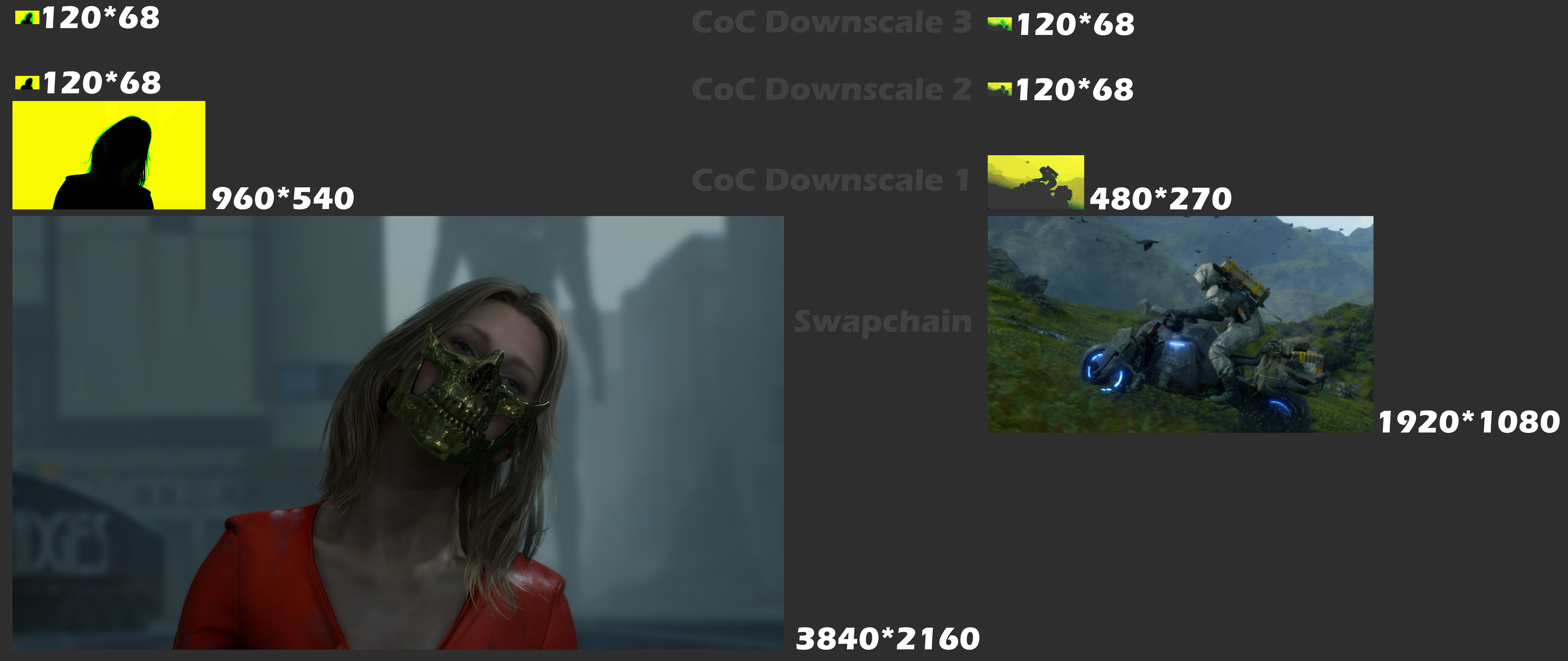
Don’t open this image in new tab…it’s 7804*3292…unless you don’t care about bandwidth
And here is the breakdown of that 4k target frame as well…
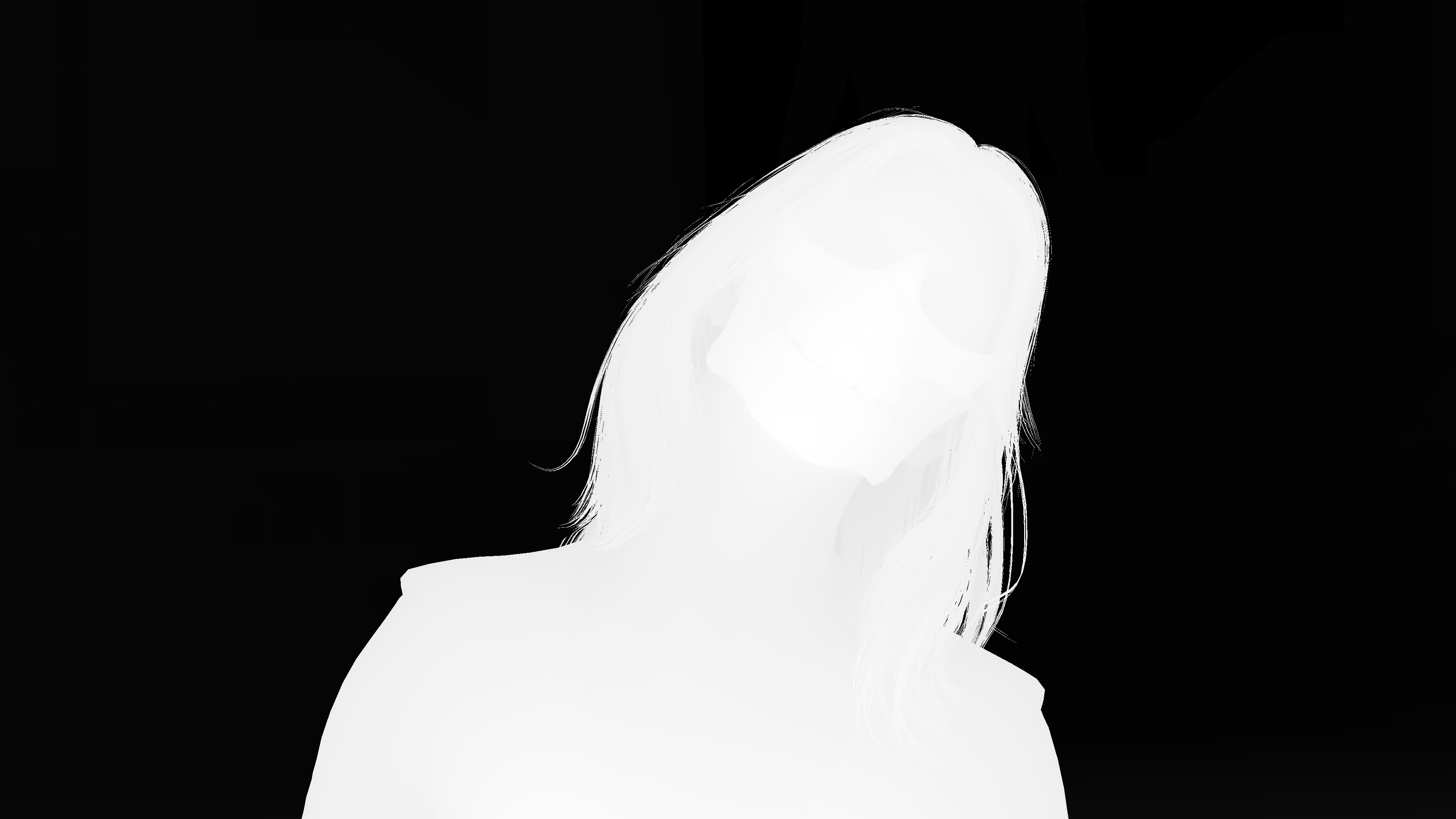
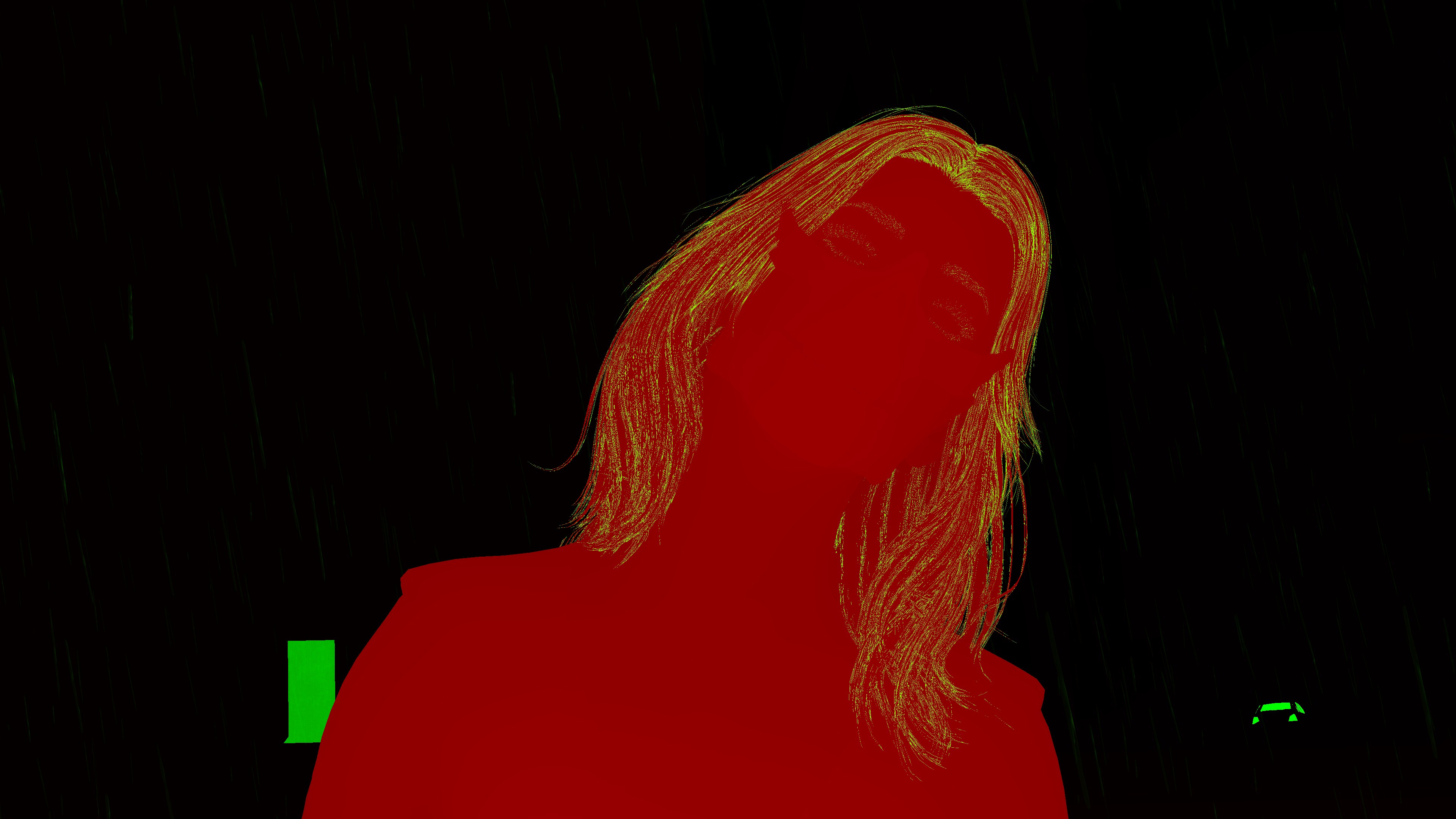


And for that purpose, some lite weight params are sent to the shader (for the entire stage regardless the steps)
CoC Params
struct CoCParams
{
     float4[] mCoCParams;   //2 elem
     float4x4 mDepthReconstructMatrix;
}
Post Process DOF Params
struct PostProcessDoFParams
{
     float4 mCoCScale;
     uint4 mTileSizeMultiplier;
}
Particle Based Flares (aka “Flares” or “Lens Flares”)
Once particle systems are all drawn, it comes the turn to a full renderpass dedicated to the Flares or Lens Flares, the length of that pass “usually” depends on the number of the flares across the frame, but don’t let the “amount” trick you as a true indication for the pass length.
Here are few examples, you will see below the Flares renderpass step by step vs the final swapchain image & how that flare looks like eventually. Just keep in mind, in this renderpass, we draw to an empty render target which called the Flare Texture, and no drawing right away to the frame, compositing of that Flare Texture is a very final step that we will discuss later just right away before presenting (aka Post-Processing renderpass).


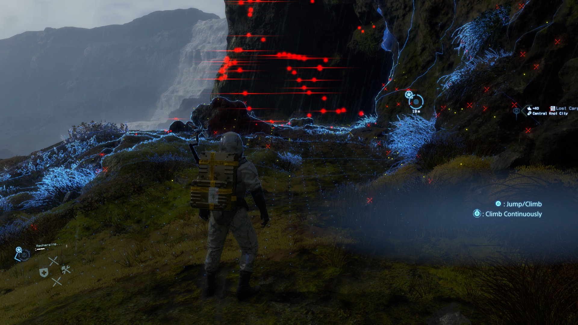

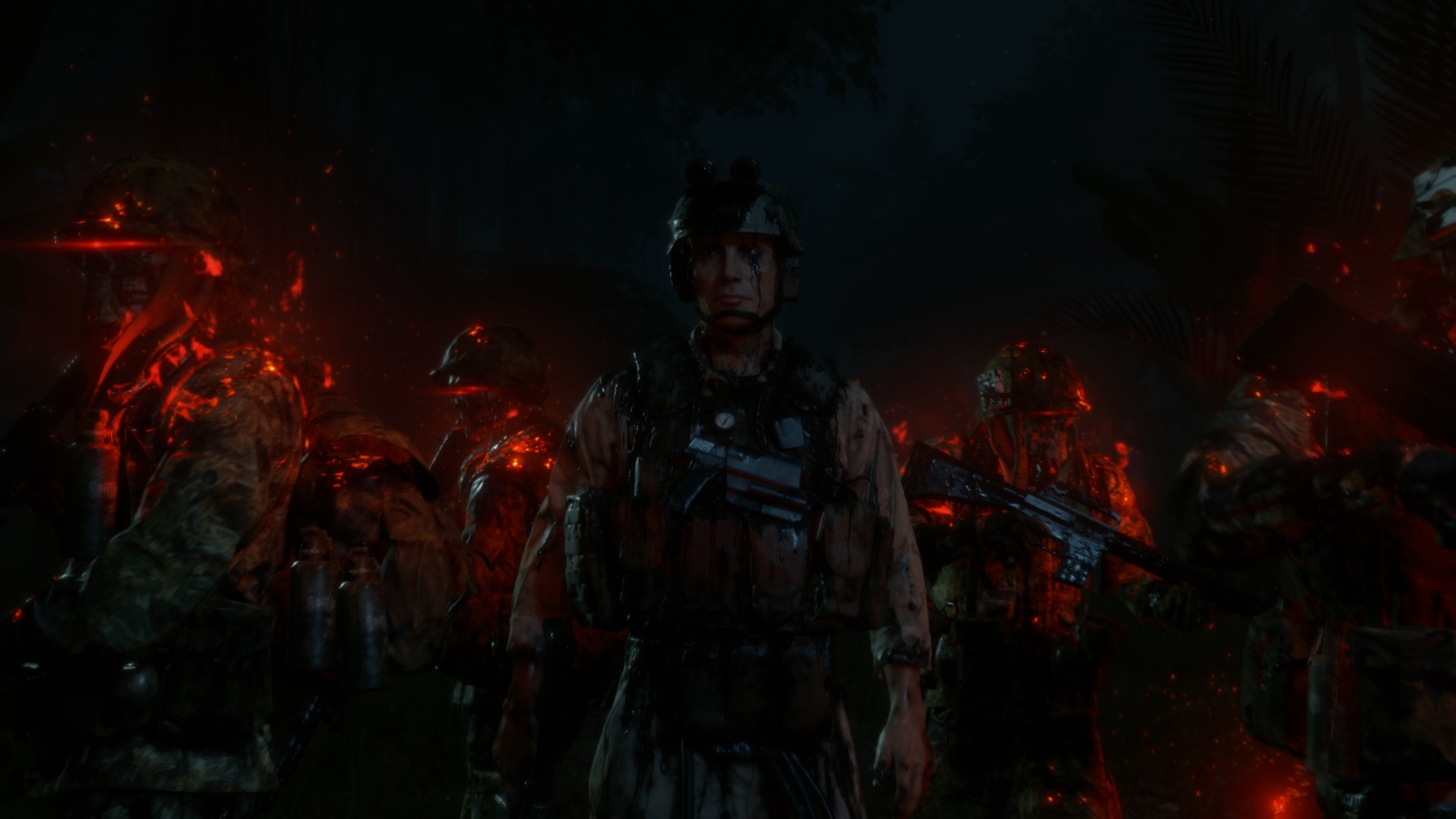
One thing to keep in mind, when a frame doesn’t have any Flares around, the game still create the Flares Texture render target and in 1/2 of the target resolution, but keeps it solid black, and use it later in the late Post-Processing. But either way, there will always be a Flare Texture in 1/2 res around, regardless there are values or not. And i find this a little bit off, where you easily can see many 1*1 passed to shaders all the way when there is no actual texture or rendertarget, but this is not the case here, it would have been much better, more performant & a lot consistent to do the same with a 1*1 for a no-Flares frame.
The Flare Texture that holding all the pretty flares details are always 1/2 of the target resolution (at most of my frames 960*540) with the format of RG11B10_FLOAT .
Regarding the inputs for this phase, there are always 3 textures of the size 64*64 and the format RGBA16_FLOAT, that is passed to each flare drawing command as instance data. So putting all together, you’ve something like that (each example is a column)


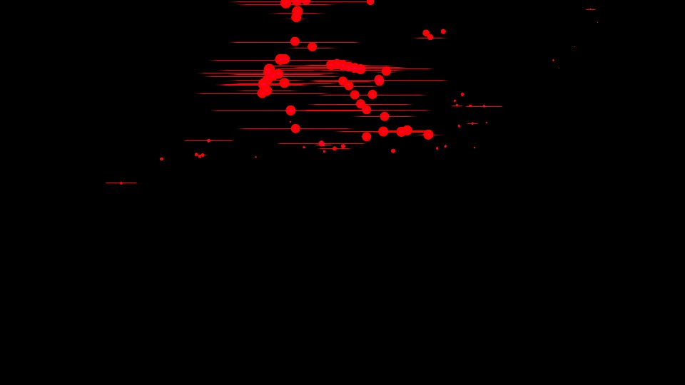


4th row is the final Flare Image that will be used in the Post-Processing pass, but in a more “readable” range for the sake of the article, not the original texture and how GPU sees it
5th row is the actual final Flare Image in it’s true range, this is actually what is used in the Post-Processing pass
6th row is the final swapchain, post the Post-Processing pass
And of course there are some lens flares data/params, that are in a limited size array of 14 entries (the maximum supported number of flares to draw per frame).
Lens Flare Constants
struct LensFlareConstants
{
     struct LensFlareData [14]
     {
	float4 mScaleAndGlobalTint;
	float4 mPositionScaleBias;
	float4 mRotation;
	float4 mStretch;
	float4 mCompletion;
	float4 mDistanceAndCompletionScaleBias;
	float4 mBrightnessAndSeed;
	float4 mTriggerSelector;
	float4 mTriggerEffects;
	float4 mTriggerShape;
	float4 mTriggerTransform;
	float4 mTriggerColor;
	float4 mTriggerOptionsAndColorCoord;
	float4[] mElement;
     }
}
While i mentioned that the draw happens here one by one as we seen in earlier games such as Resident Evil, but the difference here than what you saw before, that the Flares are mostly treated as particles, and when draw Flares including exact & similar flares, it get patched in group of instanced, just like regular particles, which was not the case at Resident Evil where similar Flares used to be drawn one by one individually. Most nontribally here, the example No.4, where all the red dots are draw in a single cmd as group of instances, and followed by an another single draw cmd for all the horizontal lines instances.
So, when saying the maximum number of flares per frame is 14, in that examples of red dots, where we’ve many flares across the frame, but in reality, we only draw 2 patches, which leaves us with ~12 flares not used yet!
Brilliant!!


And this is why i decided to call this “Particle based Flares” and not just “Flares”.
If you are into individual draw of each flare, you’re welcomed to explore those few collapsed tabs below including in true resolution all the draw steps (the ones used to make the gifs & videos).
Flare Steps Example 1


Flare Steps Example 2


Flare Steps Example 3


Flare Steps Example 4

Flare Steps Example 5


Flare Steps Example 6

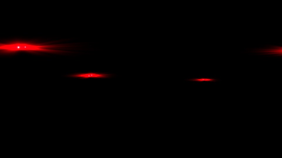
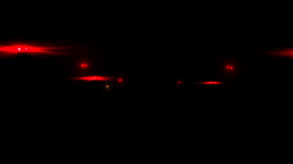
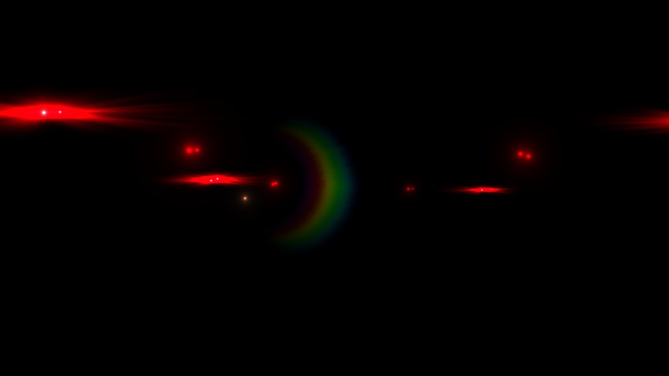

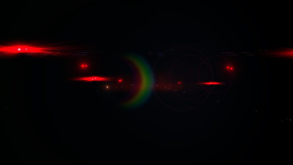
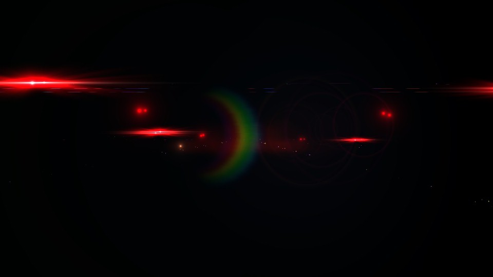

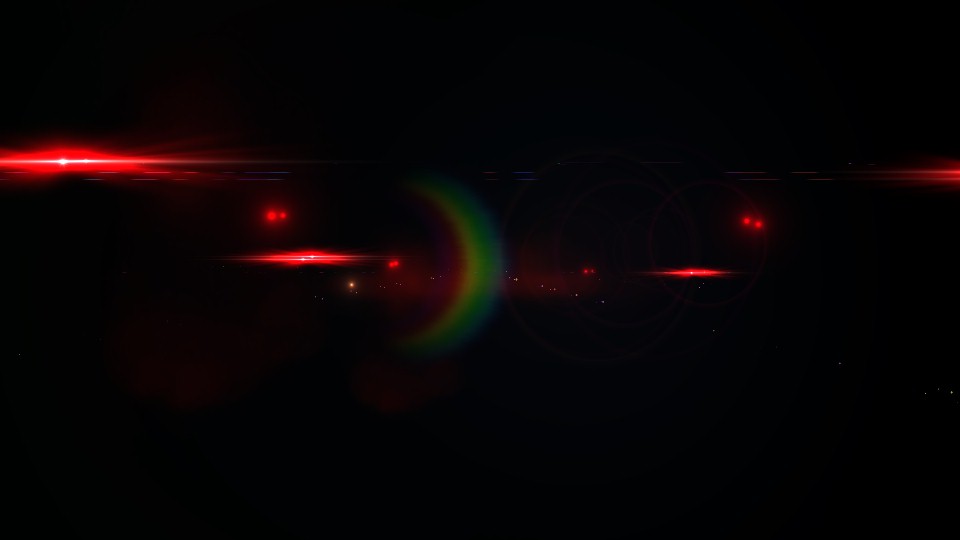
And last thing before leaving the Flares section, let’s take a moment to admire the beautiful nature of billboarding…


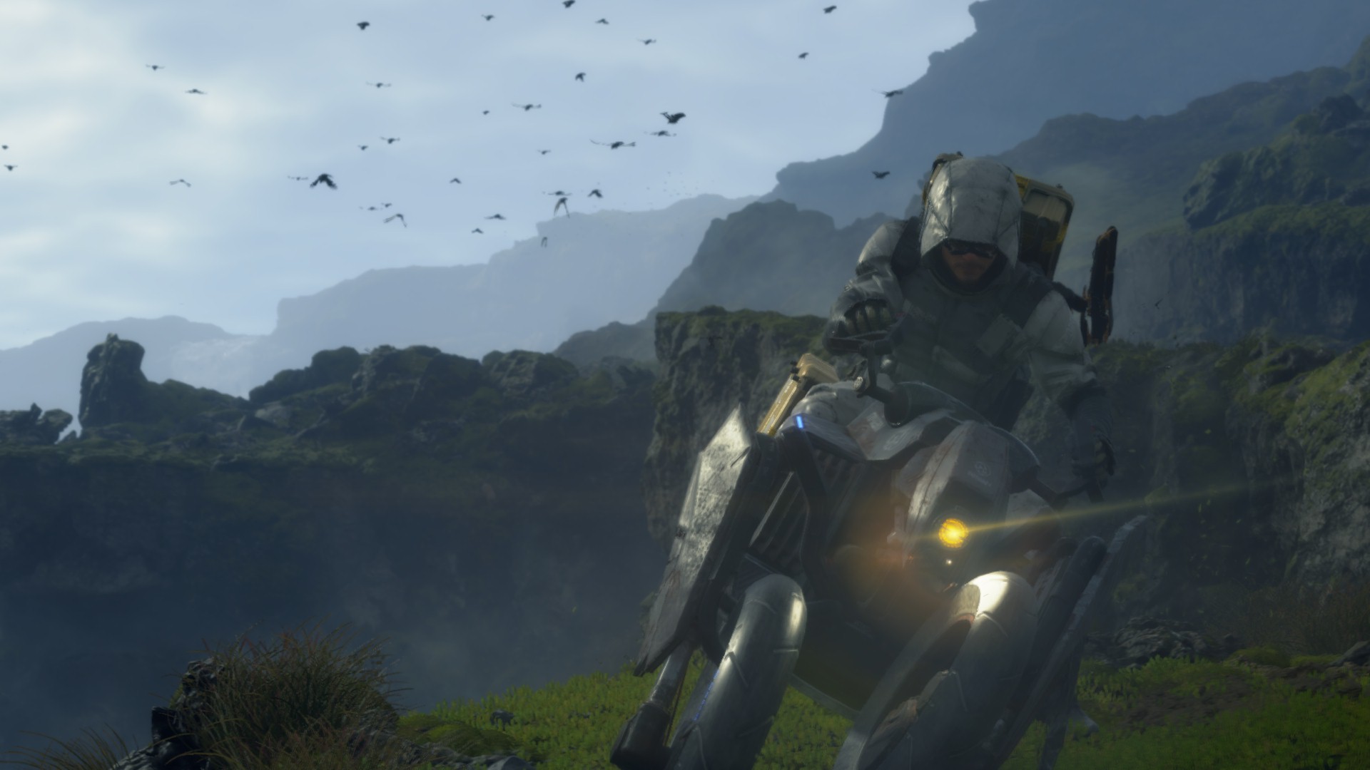
and yet, the final Flare Image looks just identical!
Post-Processing
Post-Processing is a fairly long process as you will see, but keep in mind, pretty much every thing you will see below that line, until you reach a section called “Apply Post Processing”, it is all preparations for the big moment, where the smart big shader takes everything to digest and to throw out the nice looking footage that we all desire.
One other important thing to keep in mind, that by the end of the Post-Processing pass we not only have a fully post-processed scene image, but also we get a Luma Texture that will be used shortly if the HDR was enabled in the game and supported by the hardware. So, regardless there is HDR targeted or not, that Luma Texture rendertarget get created and written to it anyways.
Bloom
1.Blit Scene Texture
Nothing fancy, just taking the current downsacled scene texture that is 960*540 (1/2 res) of the format R11G11B10_FLOAT and generate a new rendertarget that is 1/2 of that (1/4 of the target texture) that is 480*270 of the format R16G16B16A16_FLOAT, this will serve as the base for the bloom sequence of downsampling. So, basically:
1/2 Target resolution >>>>> 1/4 Target resolution
R11G11B10_FLOAT >>>>> R16G16B16A16_FLOAT
2.Downscale Scene Luminance Texture
Remember that Scene Luminance texture that we got few steps earlier between the GPU Particles and Motion Blur steps, that kinda red rendertarget. This one was already a 1/2 of the target resolution. So in this step, it is scaled down to the 1/4 of the target resolution as well. So basically by now (from the previous step + this step) we should have a Scene Texture as well as a Scene Luminance Texture, that bot are in 1/4 of the target resolution.
3.Bloom Scene Source
In this step, using the Scene Luminance and the Scene Texture that been both downscaled in the previous to steps to the 1/4 of the target resolution in addition to an intensity lookup table, as well as a 1/4 of the Depth (that was generated very very earlier) to come up with the Scene Texture that will be used to do the actual bloom downscaling….Which looks a little bit different form the actual Scene Texture at it’s current state. This output will be basically the input for the next step where bloom does the blooming…
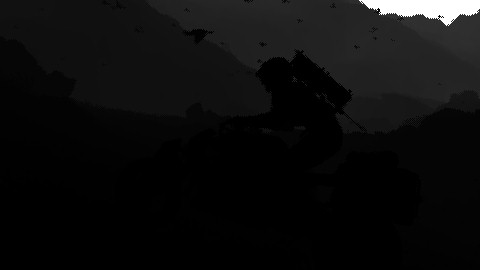

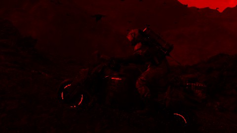
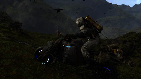

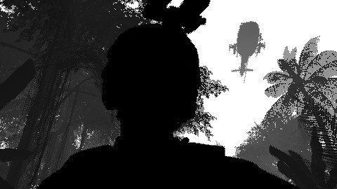

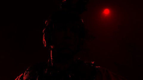

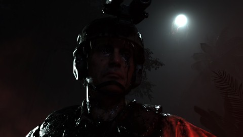
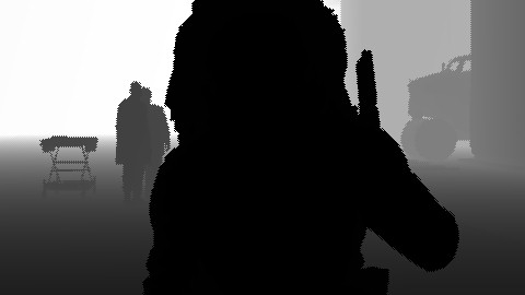


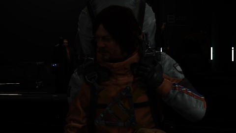


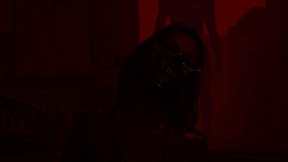


For that purpose, the shader get’s some lite weight params
Bloom Scene Params
struct BloomUniformConstant
{
     float2 mIntensityScales;
     float mSuppressFireflies;
}
4.Accumulate Previous Bloom
Using the generated Bloom Scene Source from the previous step, along side the previous’ Last Frame Bloom Texture, in addition to the Motion Vector Texture from earlier (just for the sake to know what on earth the difference between current & prev frames), we can generated the rendertarget that is really the actual base to consider as Bloom Scene Source that will be used to do the blooming (downscaling of the current scene) in the next step.
Because the output of this phase, shines more in frames that has animation and glowing objects, i’ll just keep examples that really can be noticeable, as in most frames that has no movement or no glowing lights, it is hard to observe the difference between the input Bloom Scene Source and the output one.
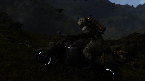


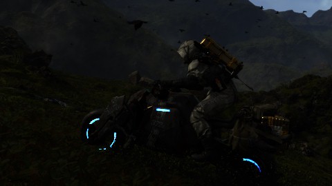
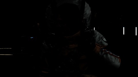
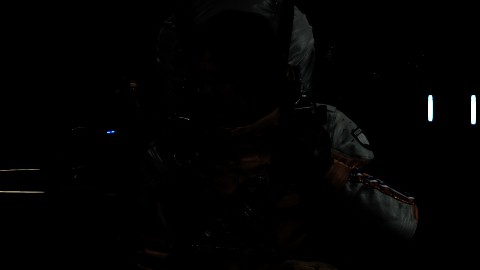
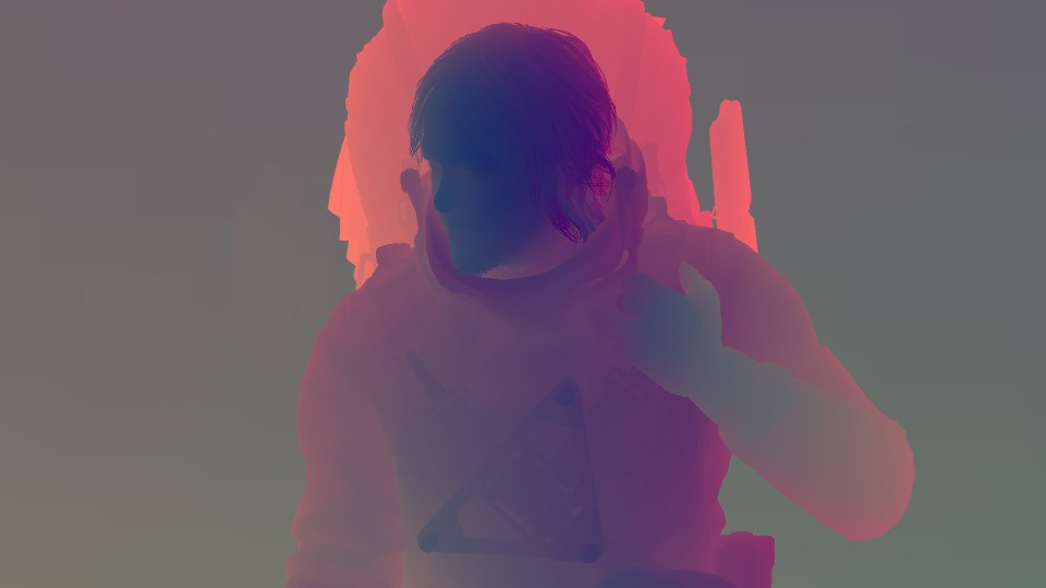
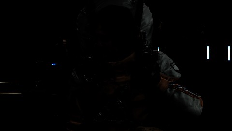
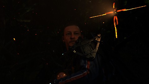
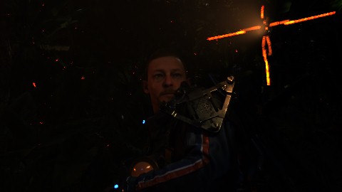
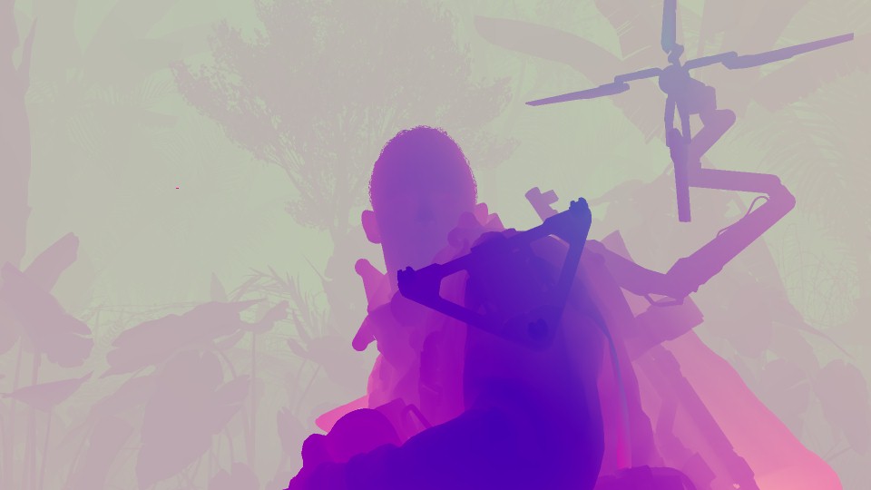
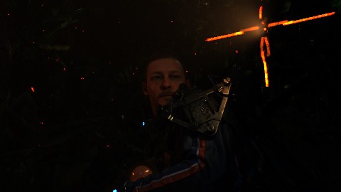
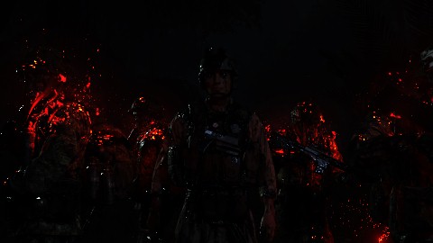
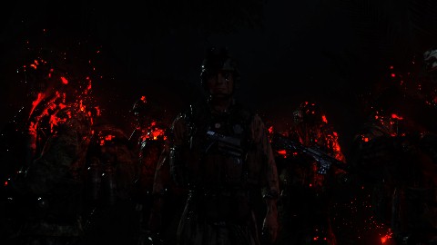
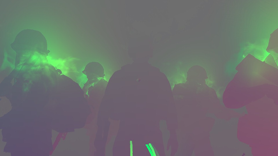
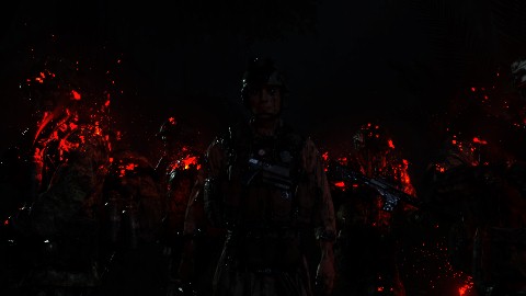
Accumulate Bloom Scene Params
struct InUniformConstant
{
     float4 mParamA;
     float4 mPostProcessUvRange;
     float4 mHalfSceneDimensions;
}
mParamA….a very descriptive name!
5.Bloom Downscaling
At this step (and the final step) of Bloom, Bloom is doing what Bloom does. Just keep downsampling and then got back upsampling, it is doing each donwnsample in 2 steps, so it does blurring horizontally, then vertically. Nothing more.


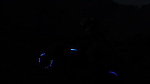
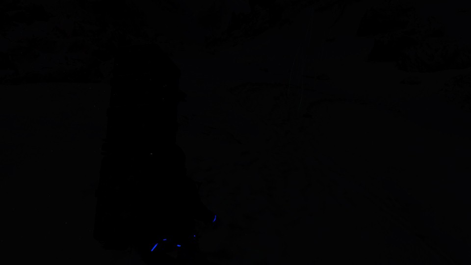


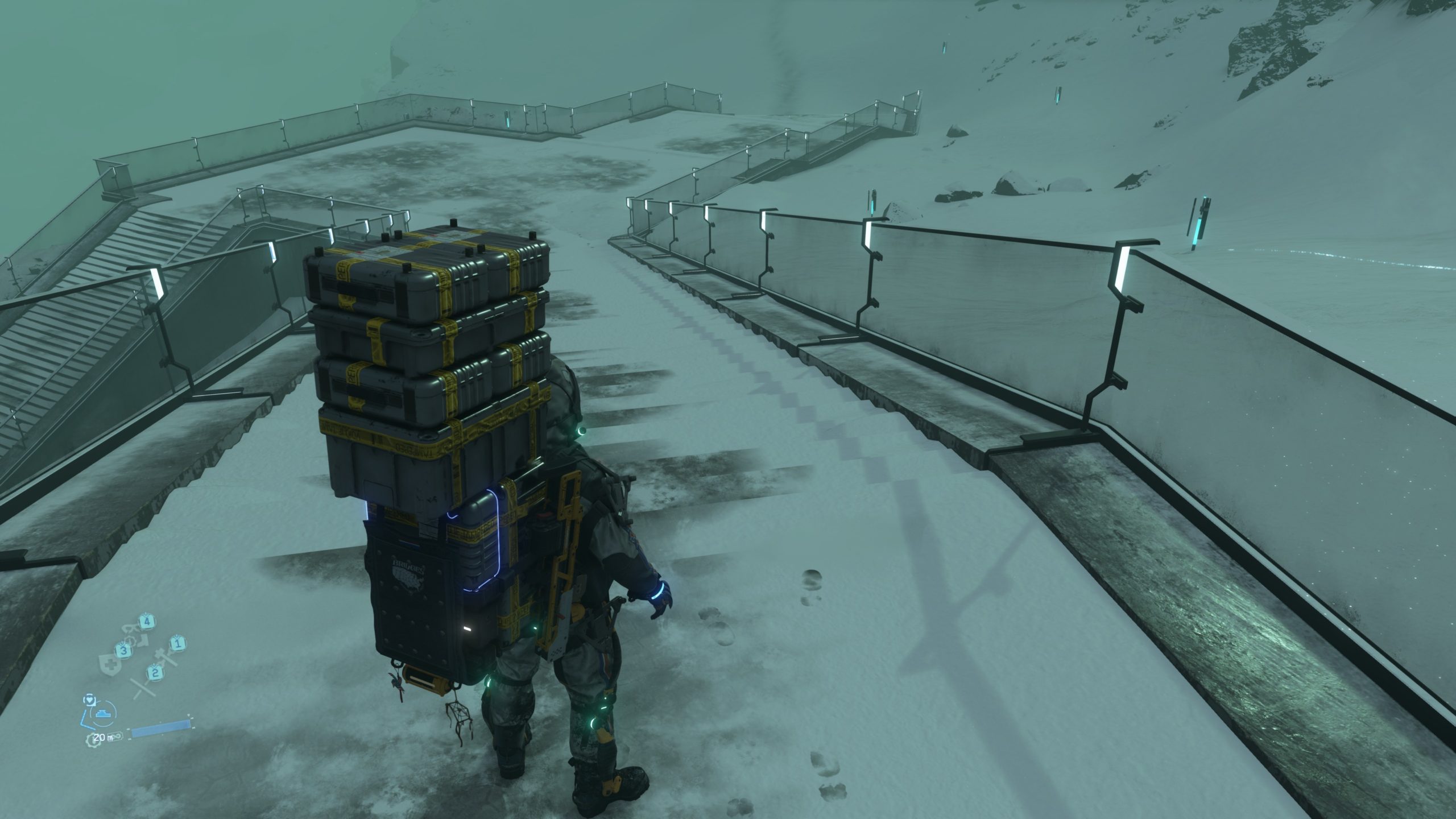


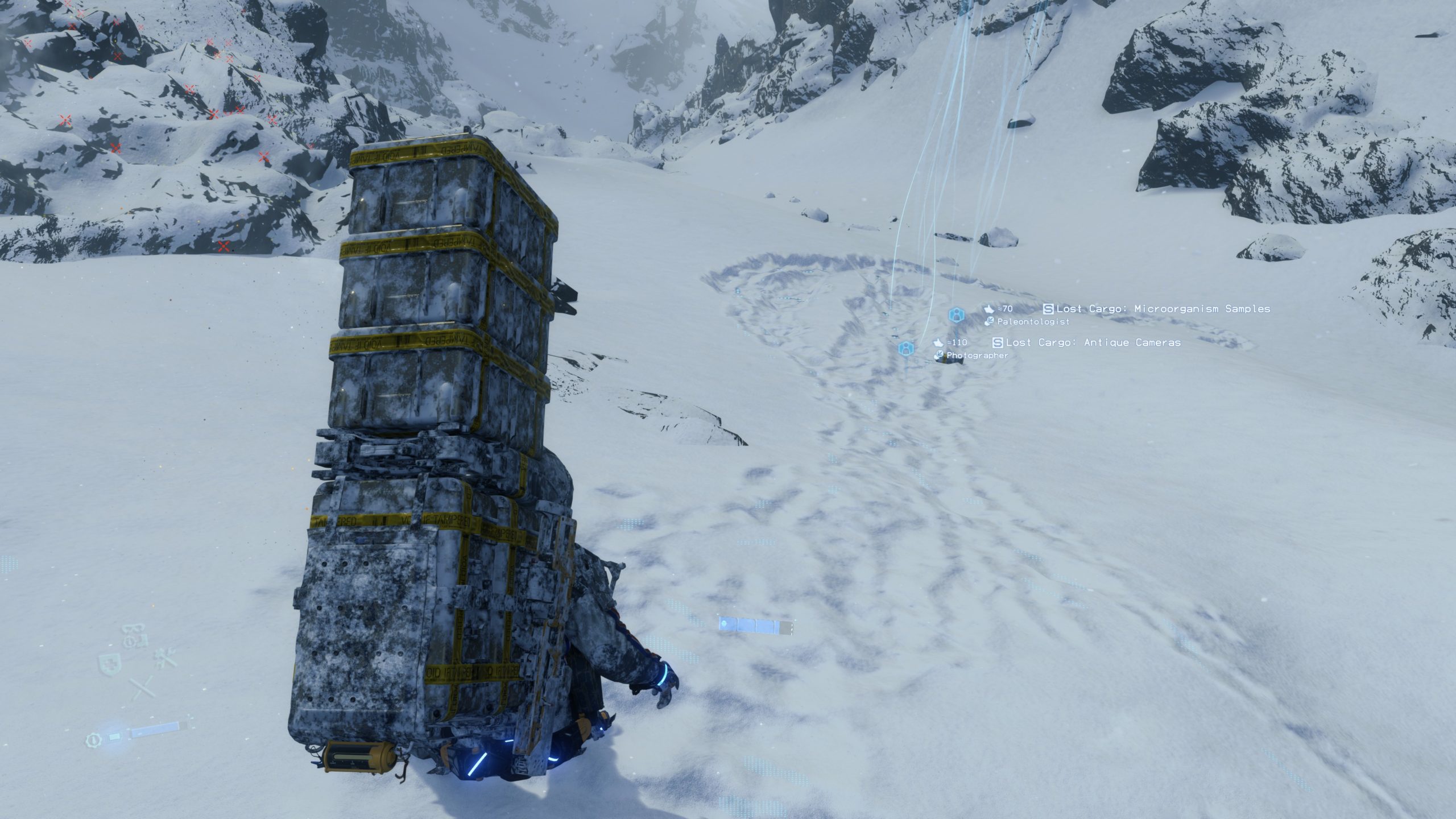
And when put in action…
At the end, as you can see, bloom here is not just about taking the state of the frame, and just scale it down and up several times, and use the output.. There are quite a few steps before that….well, … “few” isn’t a proper word! But anyways, this type of blooming the frame, is something that i rarely observed, and i do really raise my hat for it. When you look to the final frame quality of bloom, you really know why i raise my hat for that implementation.
Intermediate Luminance [Compute]
This compute always has to wait for the Bloom to finish, it is has dependency anyways. In here Bloom alongside the Luminance that was generated earlier, get together to generate the Intermediate Luminance texture that is consumed by yet another compute shader right away after this one in order to fill some render info data related to the exposure in a form of a RWBuffer of R32_FLOAT that will be passed later to the Post-Processing big shader in the next steps.


DOF Masks & Textures [Not Always]
As mentioned earlier, that DOF is cinematic only (again, makes sense for most games), and if the frame got already a CoC step, then it means that current step would take place too. Here we will go through few specific steps, in order to use the current Scene texture with the help of the CoC and the Min/Max CoC, in order to generate the NearDOF, FarDOF and DOFMask. Let’s see how this goes…
1.DOF Base
Using the current Scene Texture as well as the CoC Texture in addition to the Min/Max CoC, the shader outputs the base for the DOF work, as well as a weighting texture.


2.DOF Near & DOF Far Base
Taking that DOF base and with the use of the weighting texture, the shader can output two versions base don the ranges, each of them for the scene with the Near or Far weights.


3.Weighting DOF Near
Then starting to work on finalizing the DOF Near texture at first, buy correctly weighting it.

4.Blurring DOF Near
And then blurring everything in the near range. Now we’ve a finalized DOF Near texture.

5.Ranging DOF Mask
Do ranging for the DOF mask as well, before blurring it.

6.Blurring DOF Mask Horizontally
It’s DOF, so everything needed to be blurry anyways! Starting to blur the mask horizontally
7.Blurring DOF Mask Vertically
Then blurring the mask vertically

8.Weighting DOF Far
Final and last piece of the puzzle is the DOF Far texture, so it goes through same steps as the DOF Near texture, starting by ranging it…

9.Blurring DOF Far
Then blurring it!
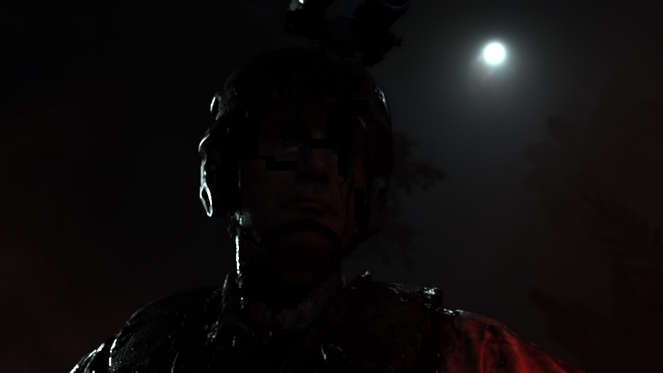
And because with more examples, it becomes more crystal clear, don’t hesitate to check out the different examples below. I made sure to put the final versions of everything, so you can get an idea from different cases.


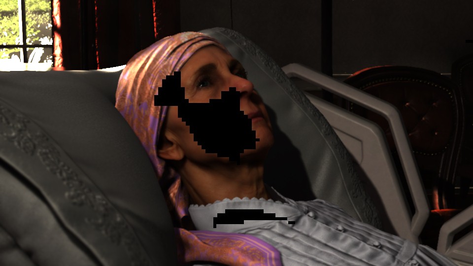
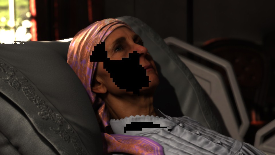


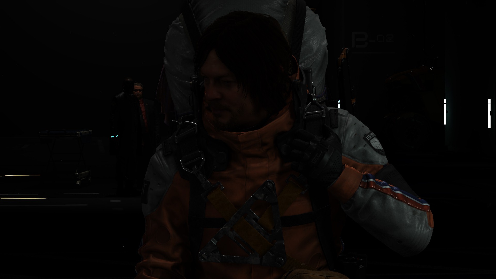
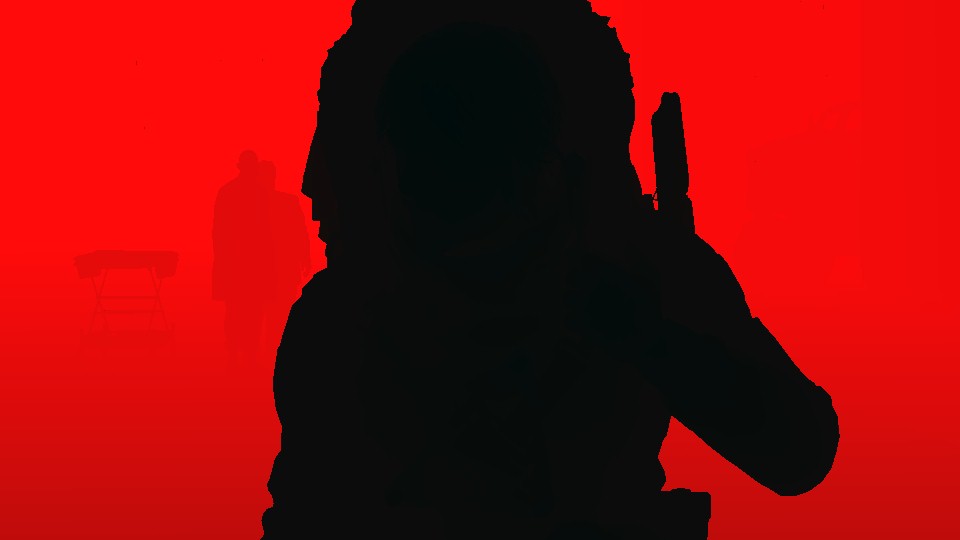
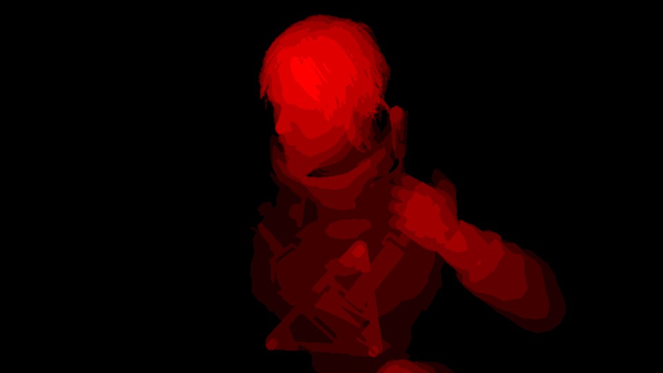


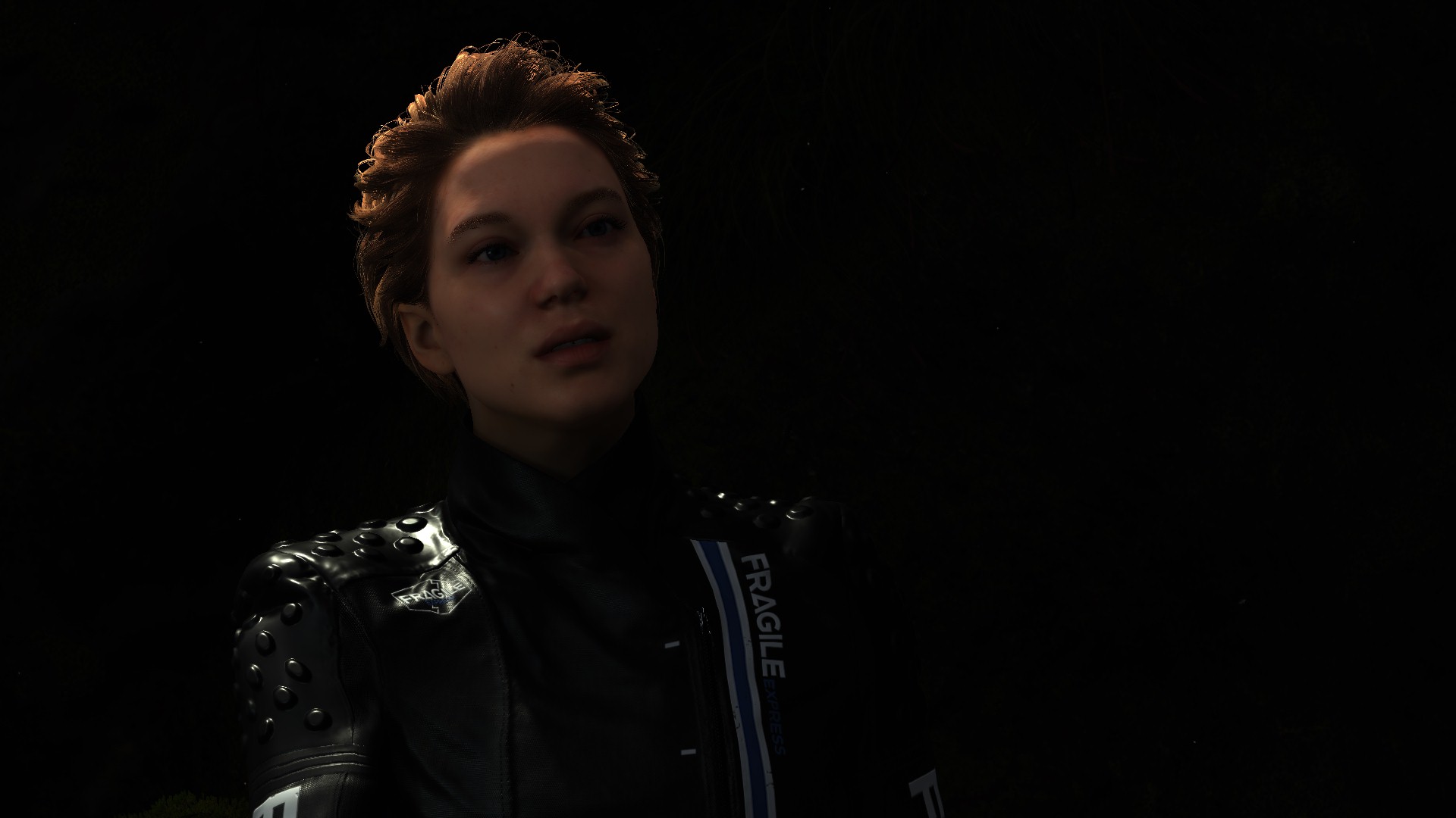


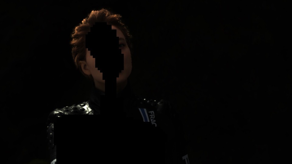
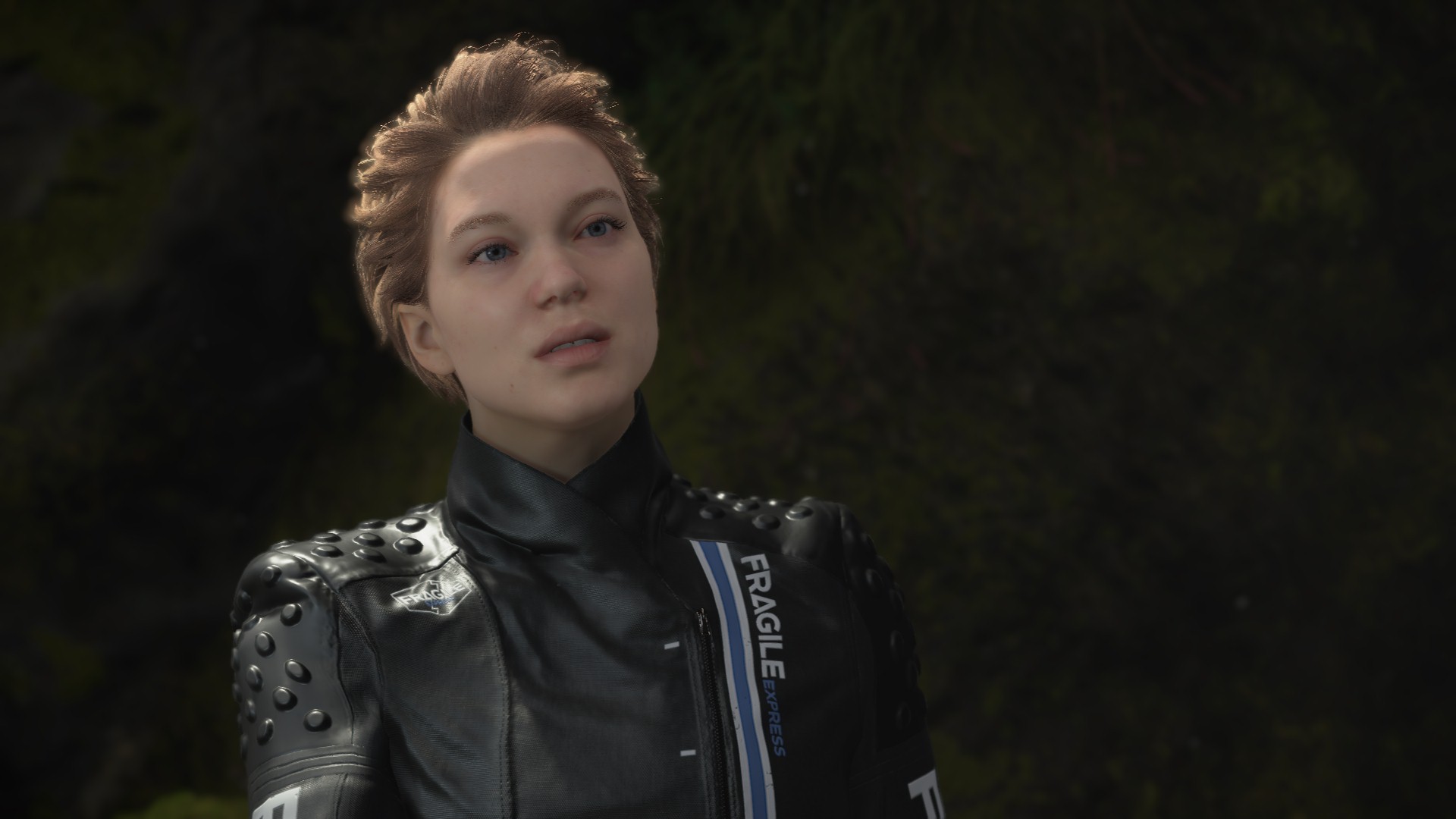


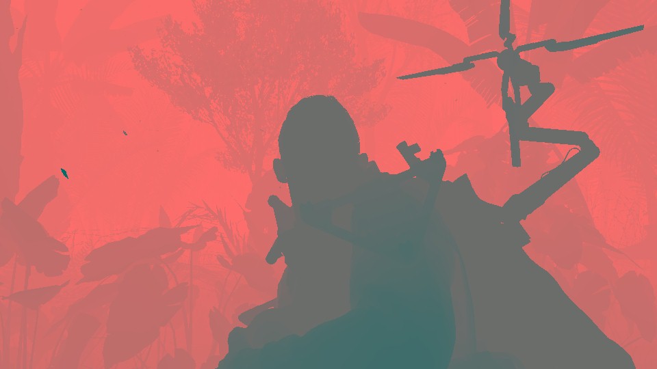
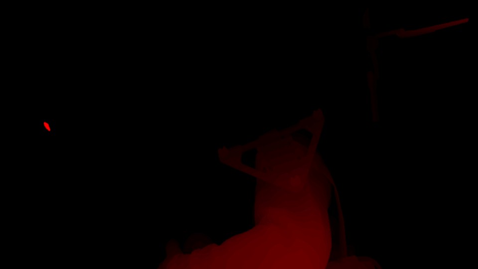
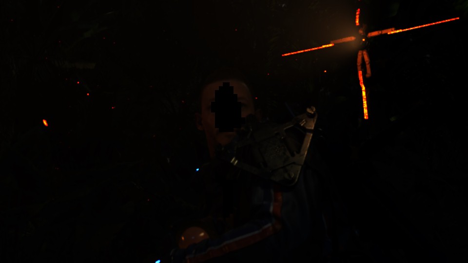


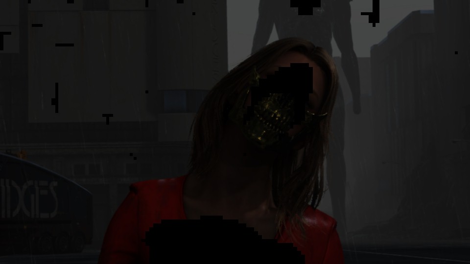
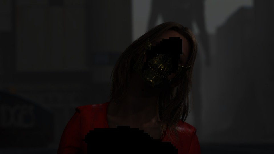
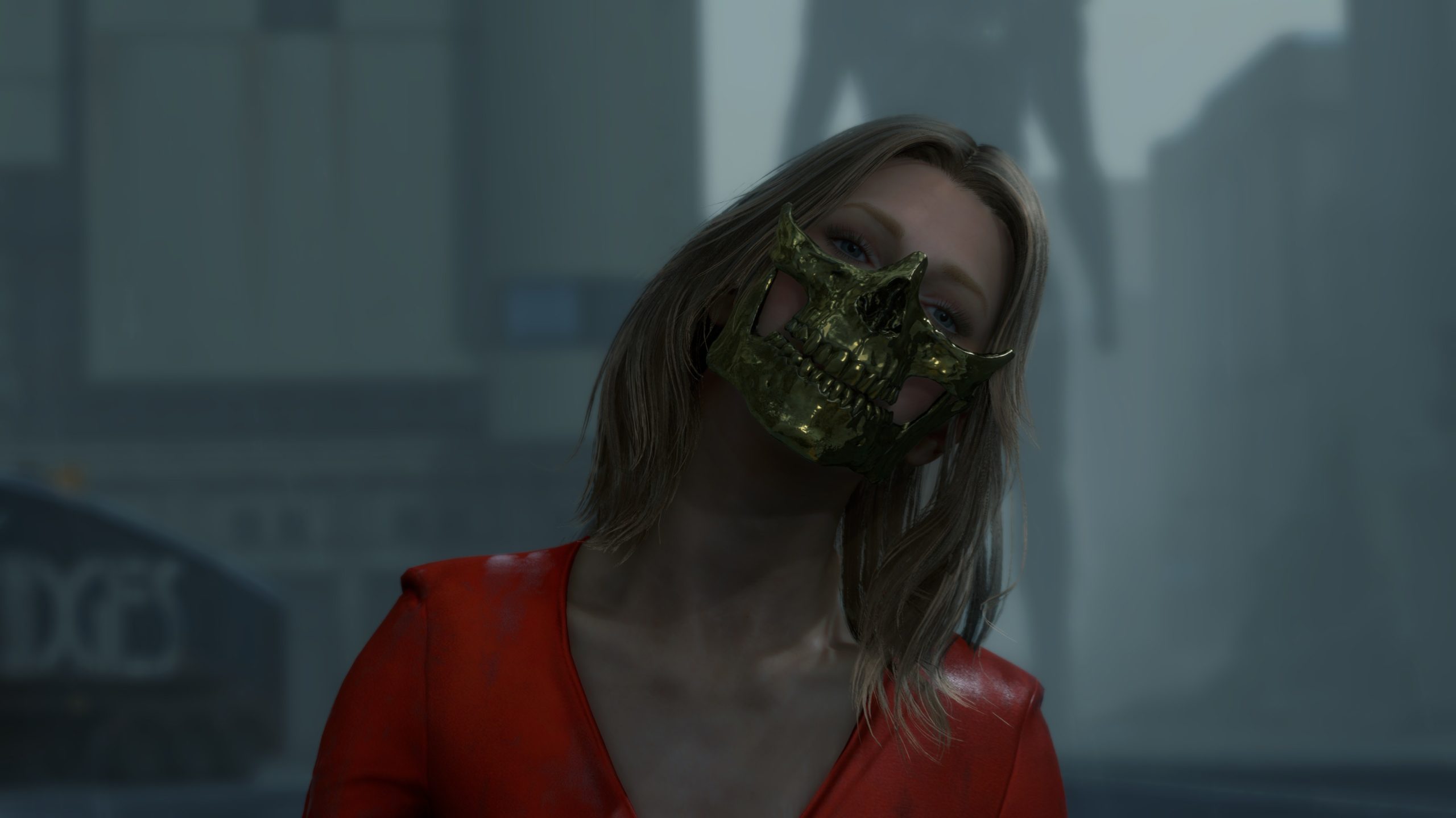


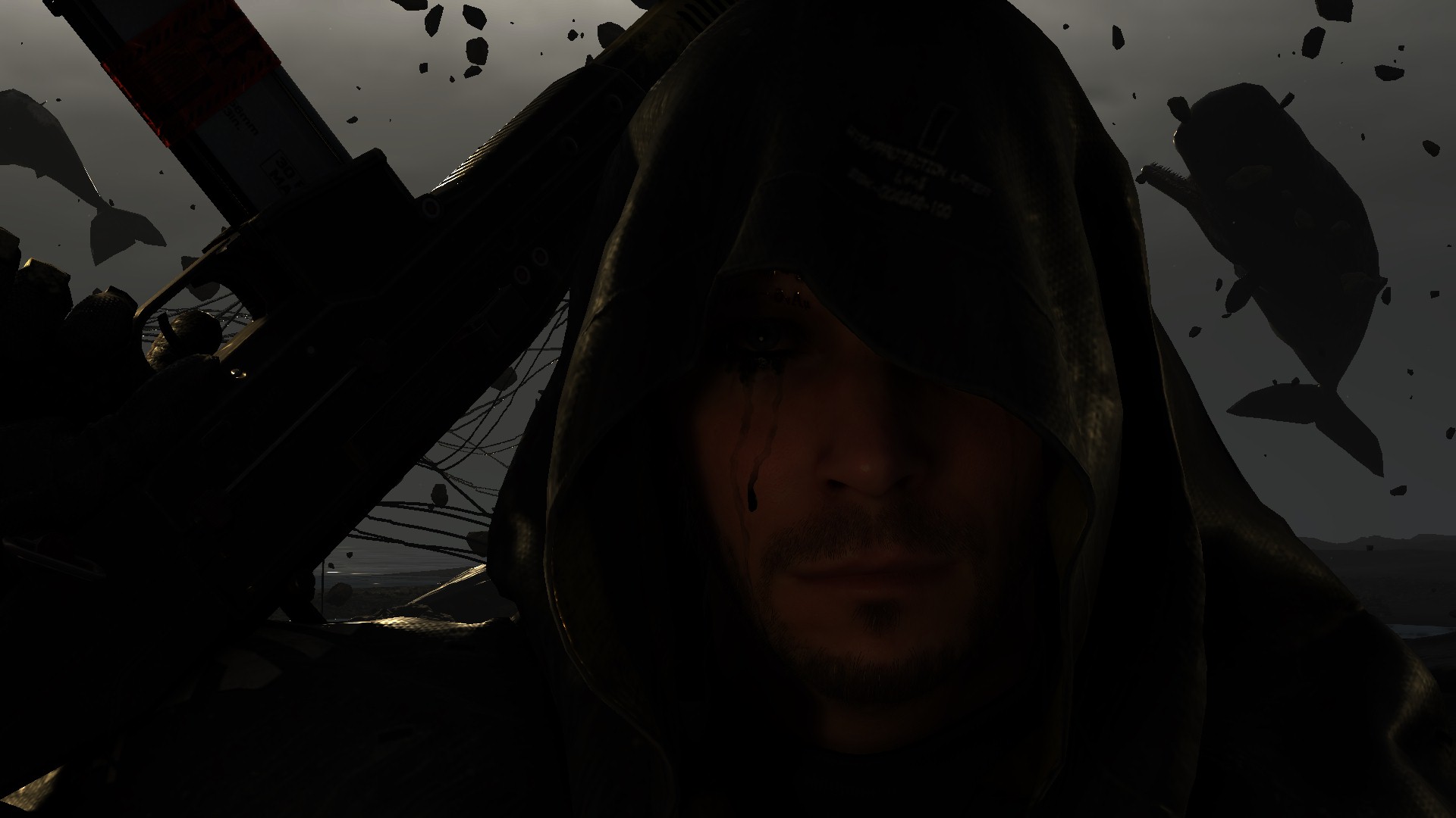
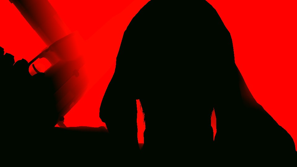

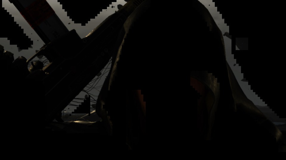
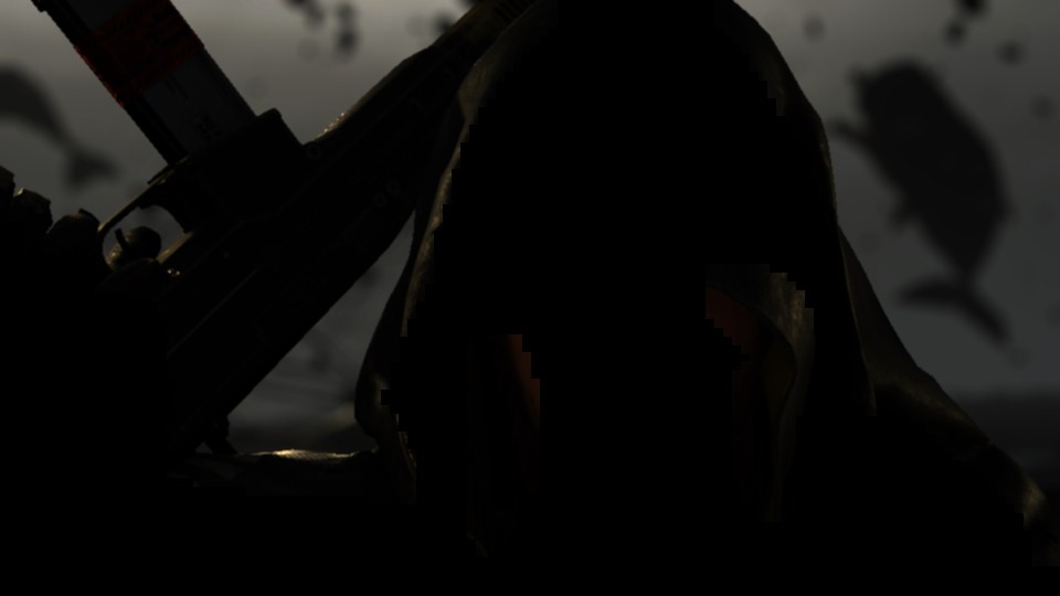

And to put it all in one graph, just in case you got lost,
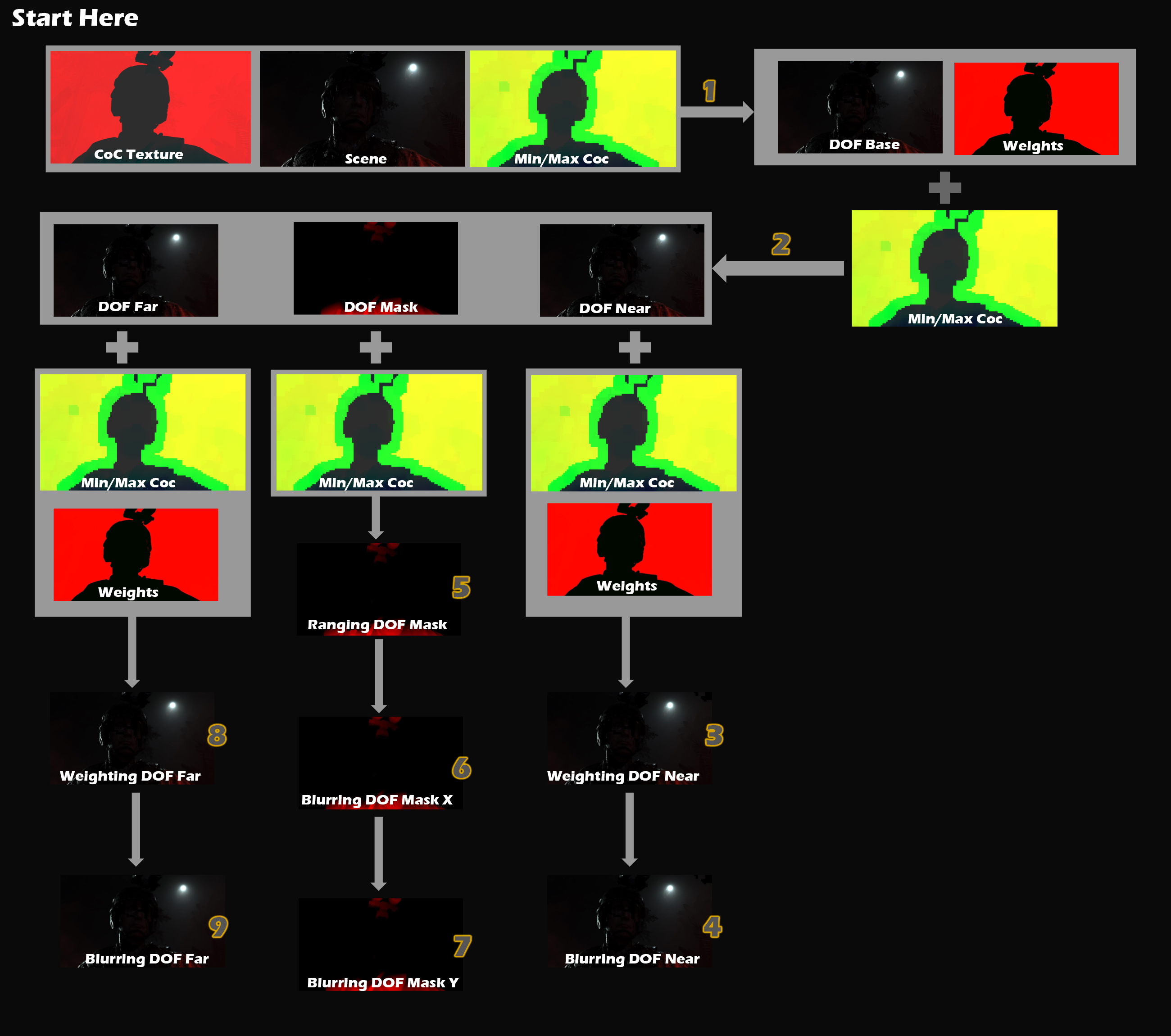
During all those steps, there are quite a few interesting params that go between the different calls
DOF Base Params
struct PostProcessDoFParams
{
	float4 mCoCScale;
	float4 mTileSizeMultiplier;
}

struct mInUniform_Constant
{
	float2 mOneOverTextureSize;
	float4 mPostProcessUvRange;
	PostProcessDofParams mPostProcessDoFParams;
}
DOF Near and Far Params
struct mInUniform_Constant
{
	float2 mCoCRange;
	float2 mOneOverTextureSize;
	float4 mPostProcessUvRange;
	float mOcclusionWeight;
}
DOF Blurring Params 1
struct mInUniform_Constant
{
	float4 mPostProcessUvRange;
	float2 mOneOverTextureSize;
}
DOF Mask Ranging Params
struct mInUniform_Constant
{
	float2 mCoCRange;
	float2 mOneOverTextureSize;
	float4 mPostProcessUvRange;
}
DOF Mask Blurring Params
struct mInUniform_Constant
{
	float4[4] cKernel;
	float4 cPostProcessUvRange;
}
Now DOF pass completed it’s work and generated all the data needed by the big post-processing shader in the next step.
Apply Post-Processing Stack
Yet, all those post-processing previous steps, were actually about just preparation. Preparing Bloom, preparing DOF, Flares,…etc. Now comes the time where everything we’ve worked hard in preparing, comes together as inputs for a single fragment shader that will apply them one by one to end up with the Final Scene pretty image as well as the Luma texture we mentioned at the start of the Post-Processing section (needed later after the UI composite for HDR purposes).
With all that set, here is all the inputs that you are already familiar with, and where they came from and how they got generated, alongside the final outputs of that final Post-Processing step.
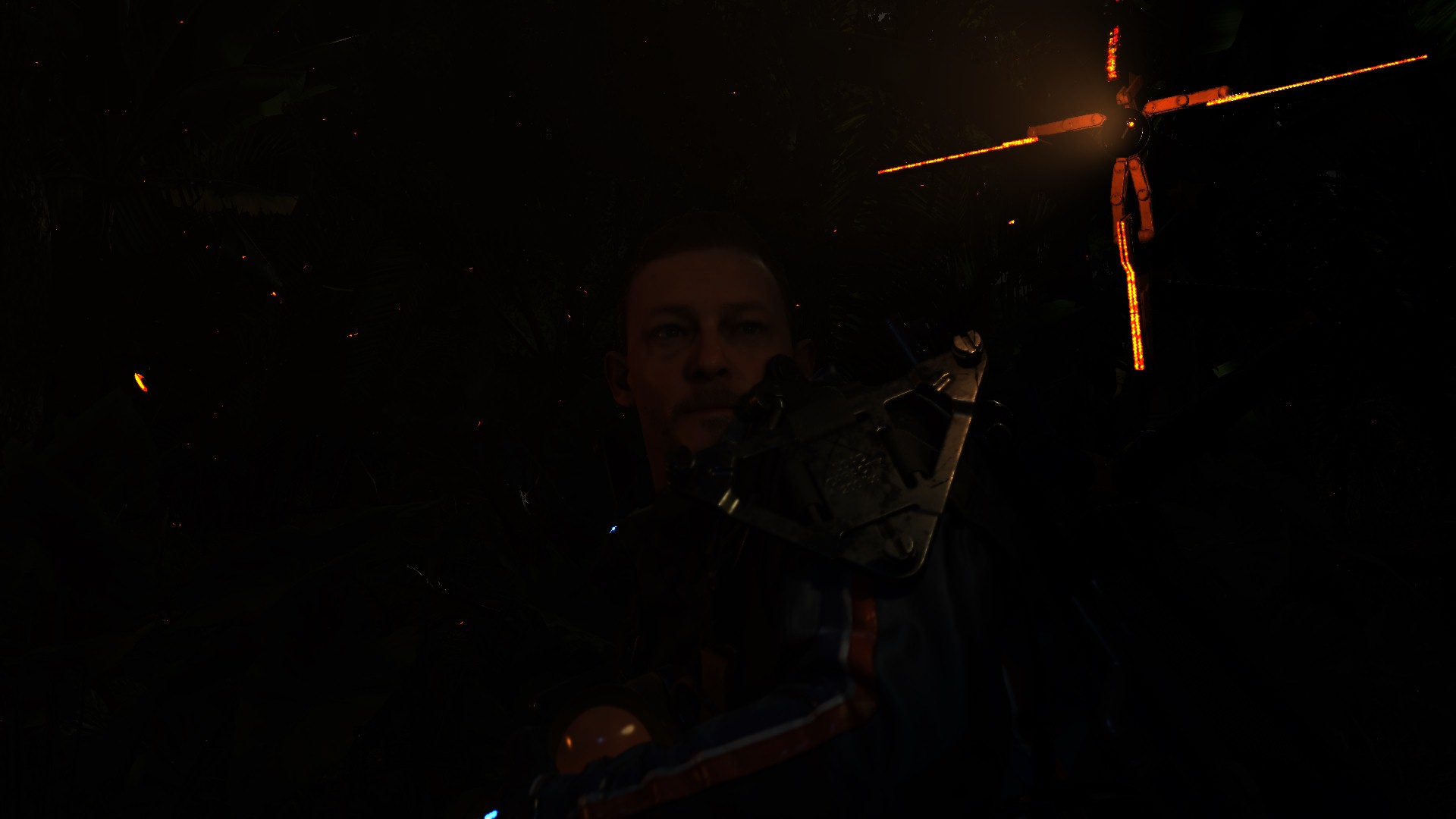
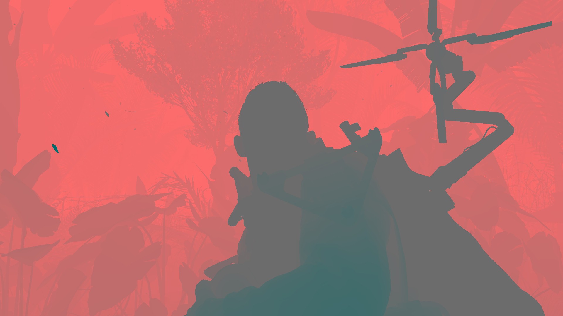


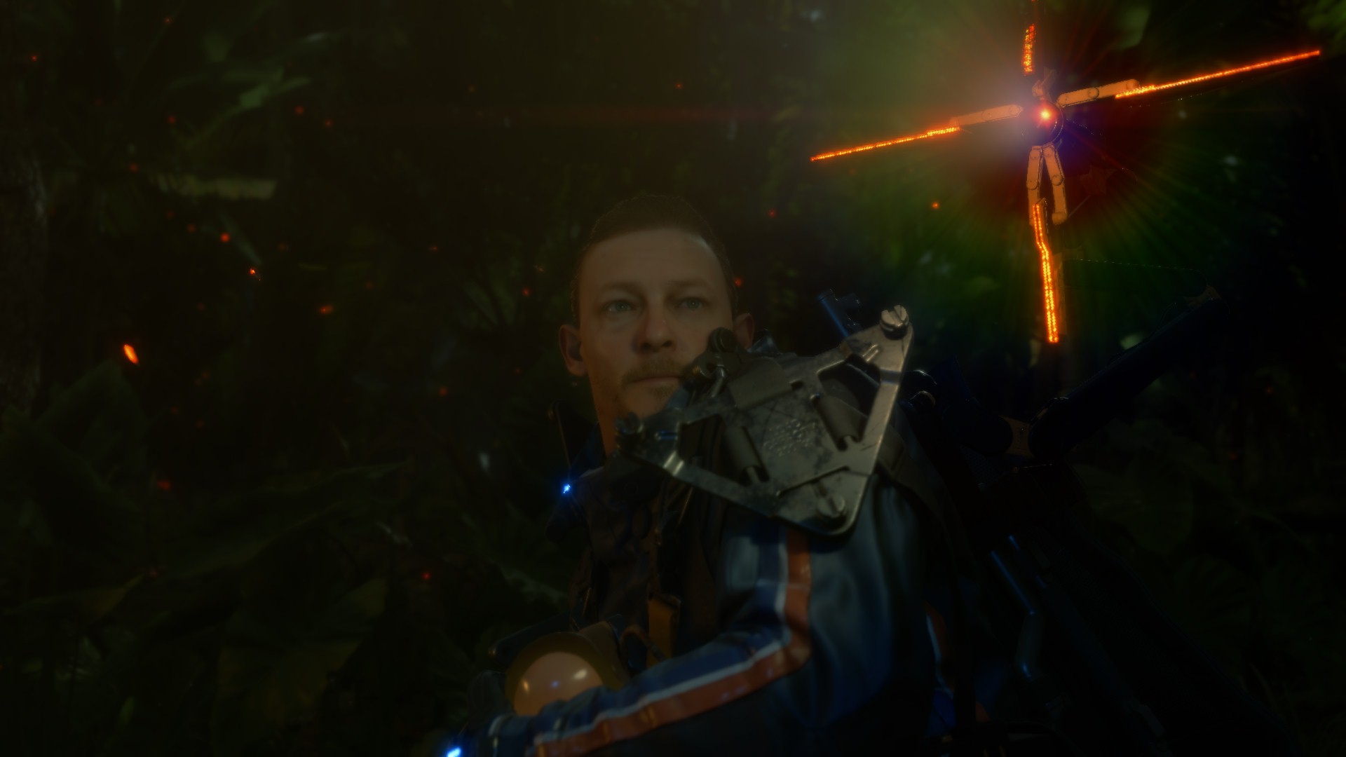

Now you would be asking yourself, during all those previous steps, we were looking at very pretty frames, so why choosing that so-so frame to showcase the final Post-Processing impact, where there are a lot better and more realistic frames?
Well, the answer is simple, it is very very very hard to find (what i call) a golden frame to use. For each step, i try to use frames that can give the best idea about the in-s and out-s of the step, and it is near impossible (within ~500 different frames) to find a frame that has DOF, Lens Flares, Bloom, Light Shafts together. You can easily find flares + Light Shafts during gameplay, but not DOF. Where in Cinematics, you can very very easily find DOF everywhere, but not always can find Flares or Light Shafts, or even both at the same time. So yeah, this frame might show a plastic Sam, and it is not my most beloved frame from this game, but it is the ones that allowed me to have all effect and their inputs demonstrated. Not sure if that was planned and in purpose, to try as much as possible to have “relaxed” effects per frame, to avoid some possible performance issues, or it is just a matter of bad luck in getting many frames that are stacked with 100% of the effects stack…not sure.
So with that said, here are below a collection of some of the good looking frames, before Post-Processing apply vs after. If you seeking all the inputs and details, it will be in the collapsible tabs below those images.

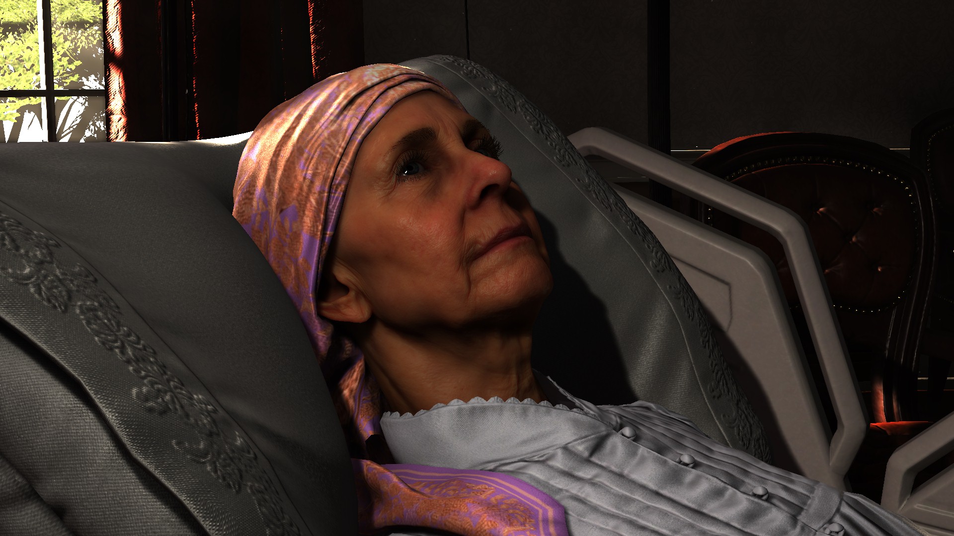

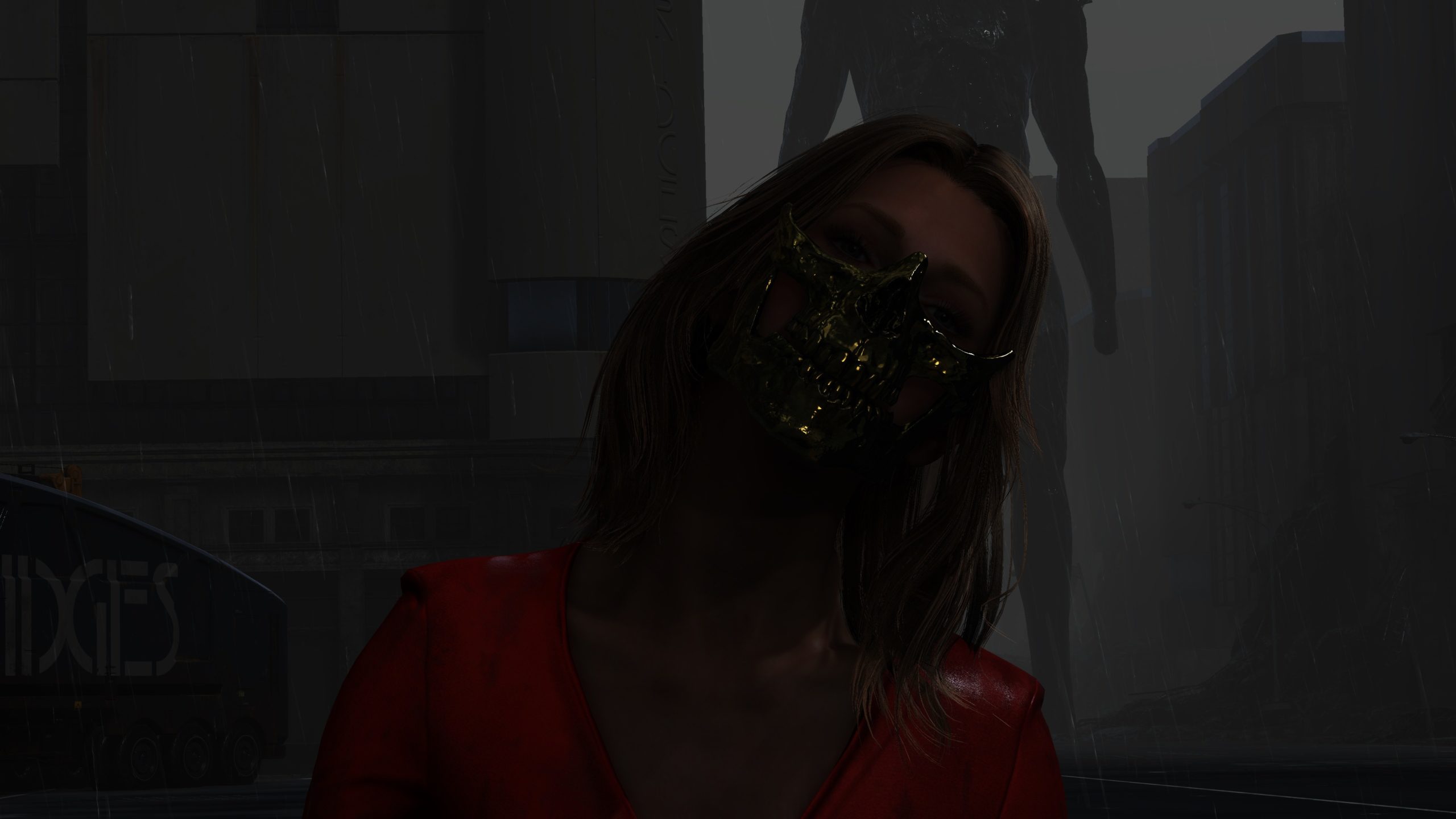

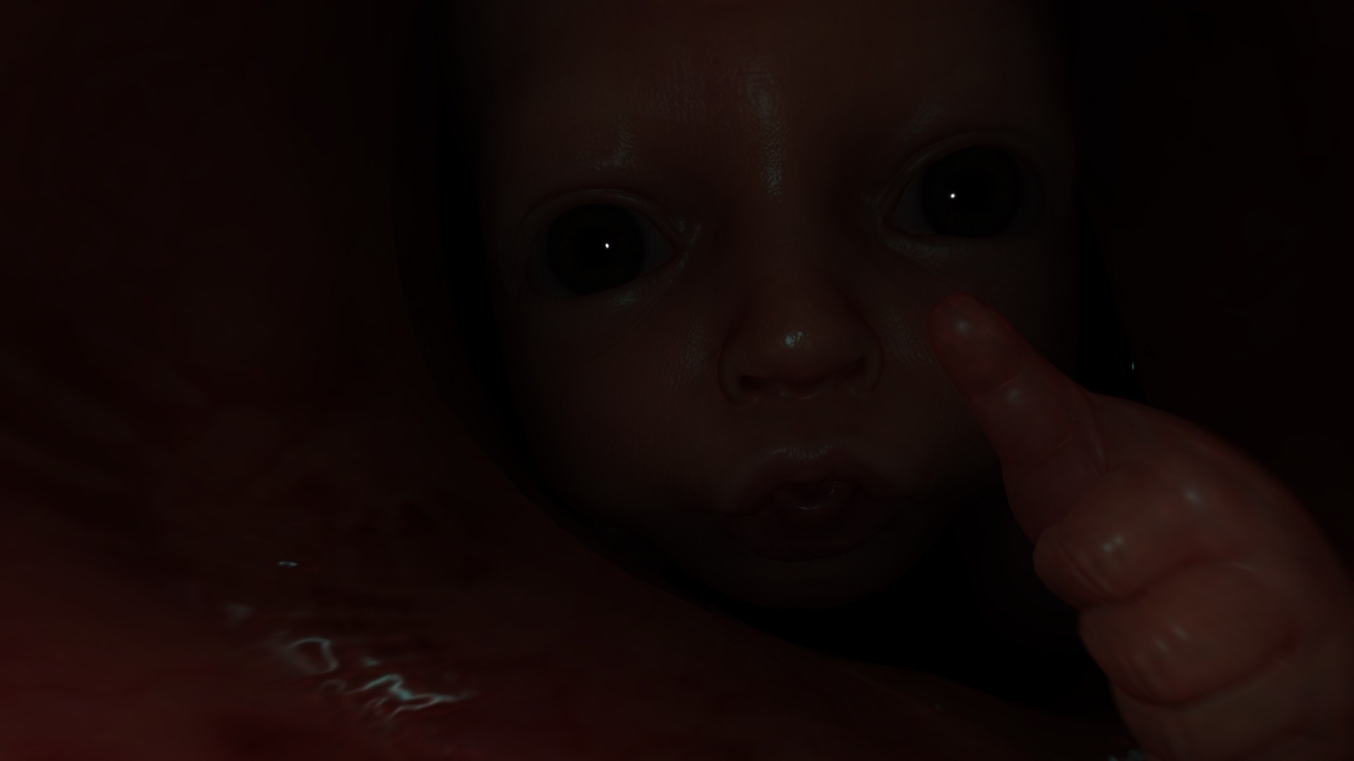
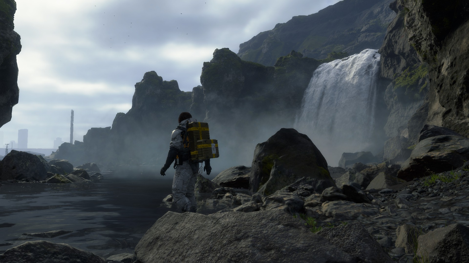


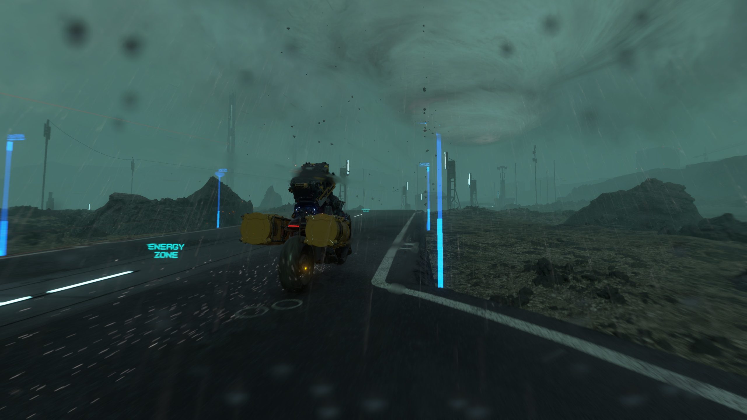

and some more
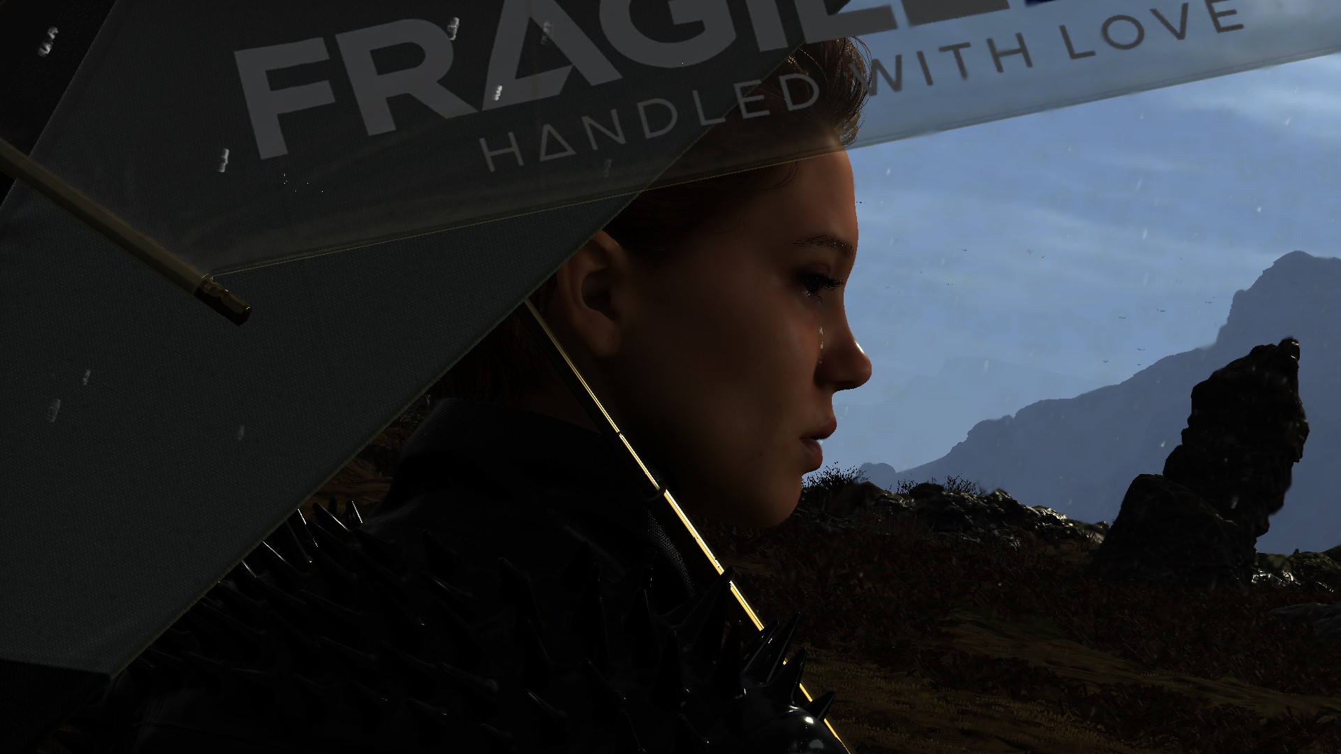

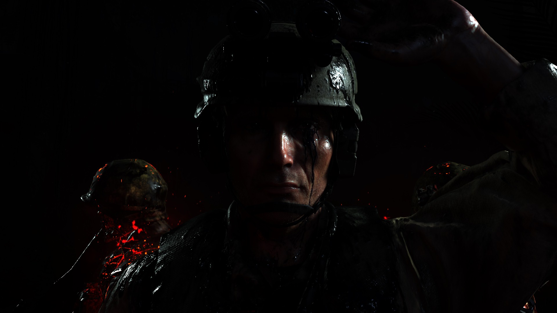
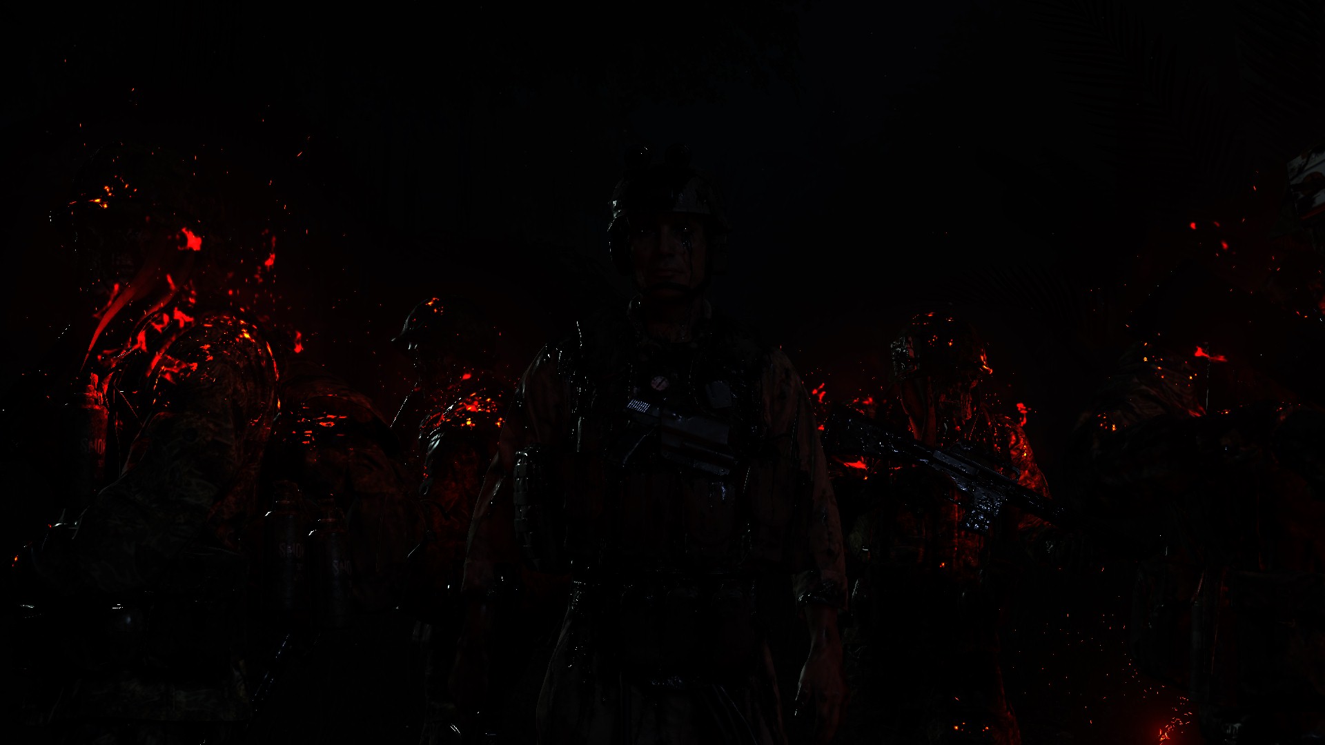

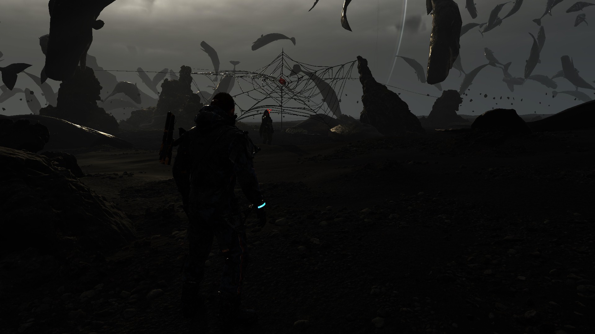
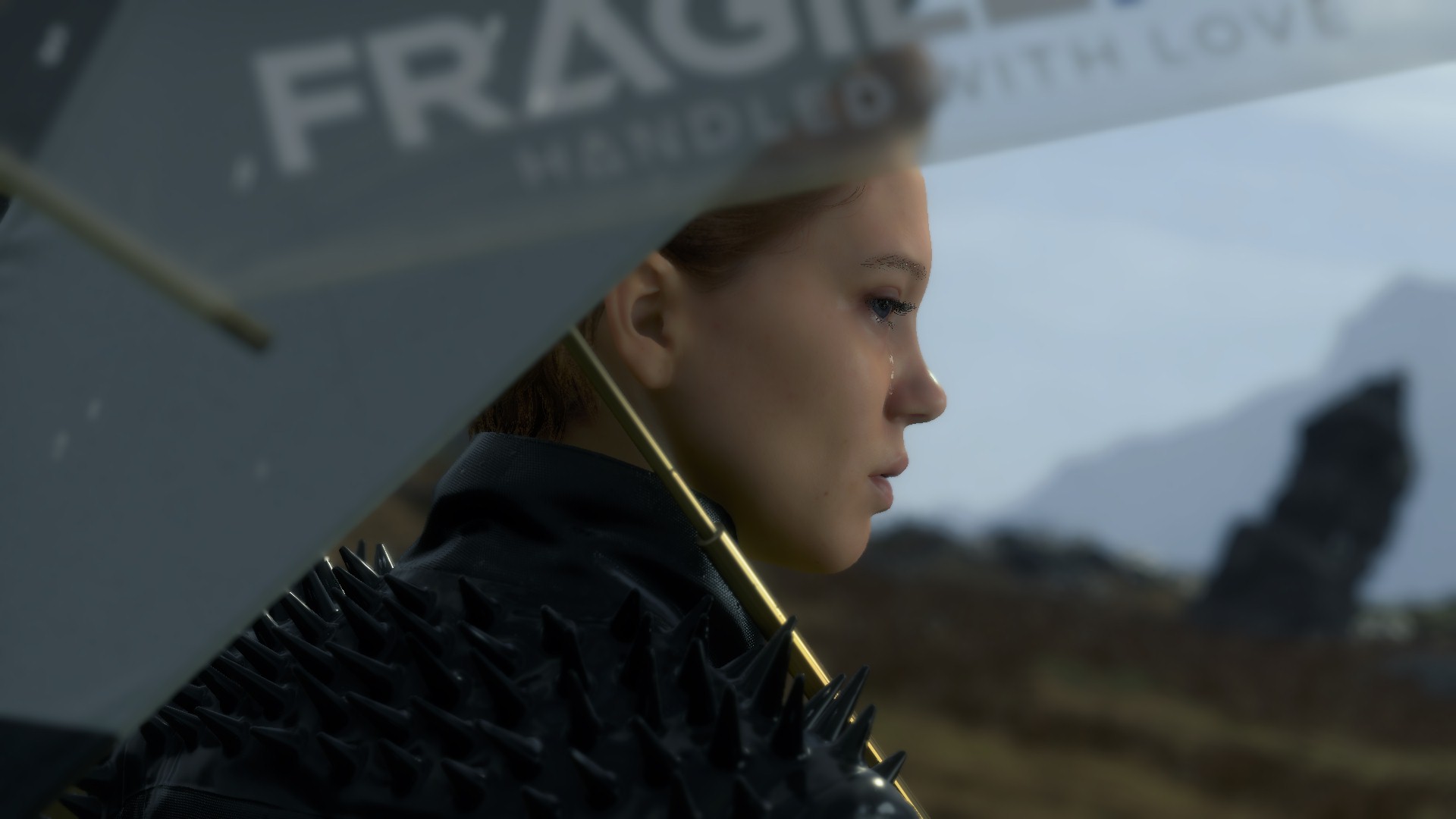
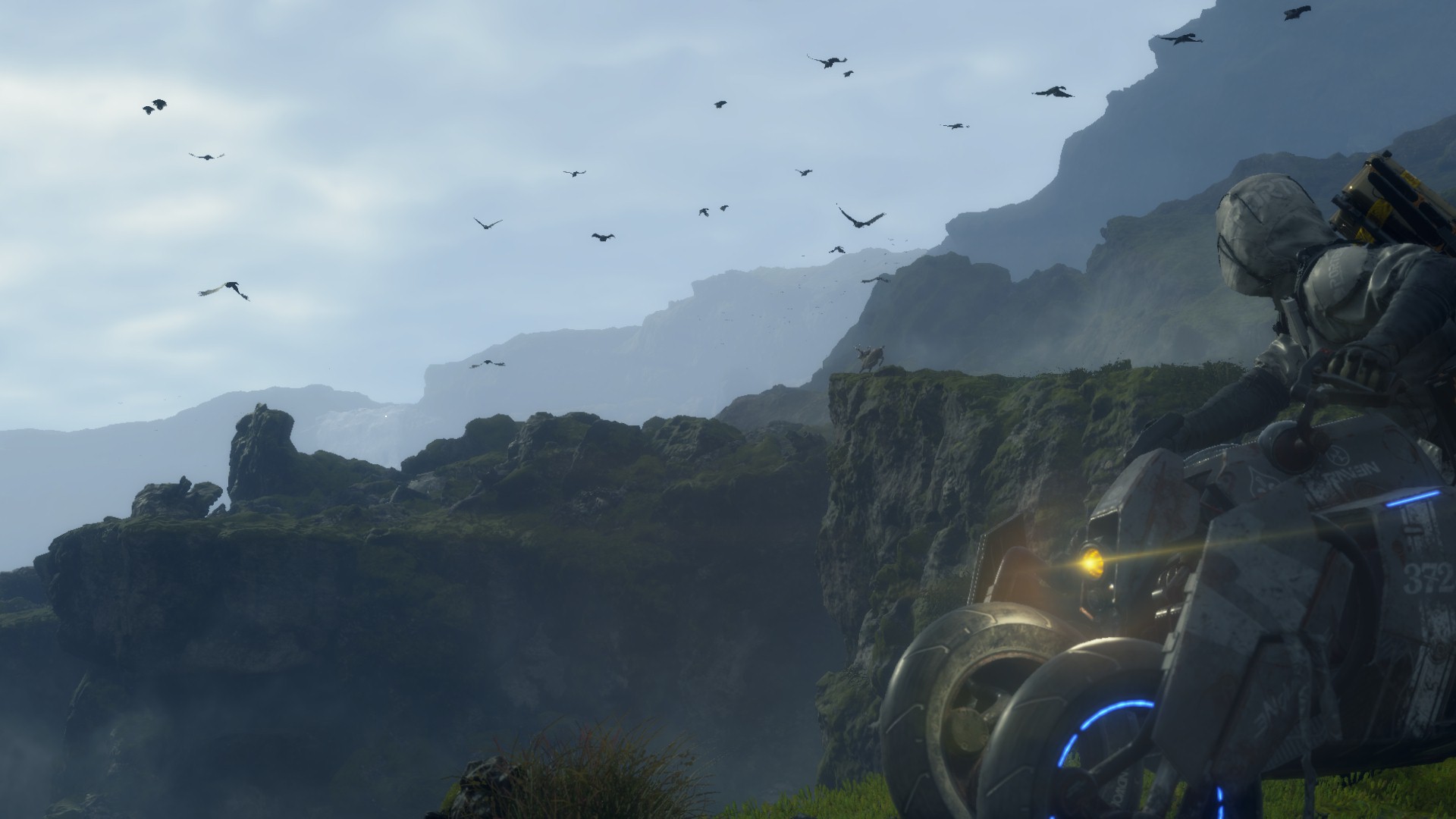


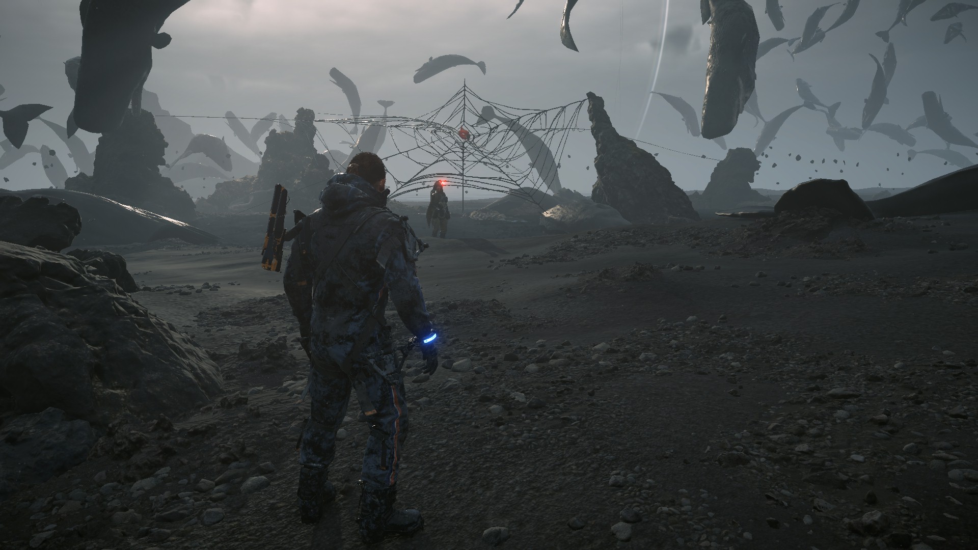
And for all the details of those frames is inside that collapsed tab. Be careful,…it’s A LOT!
Post-Processing Example 1 to 12 Breakdown
You will notice that whenever a post-processing feature is not exist in the current frame we processing, the inputs needed by that post processor will be just a blank placeholder that is 4*4 most of the time, which is good. But sometimes, there are larger placeholders utilized that are 1/2 or 1/4 of the target frame.
Flare Steps Example 1


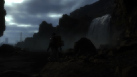


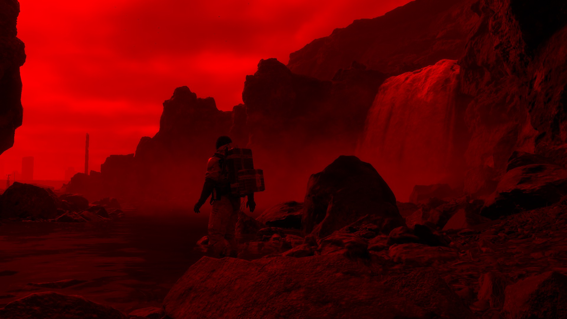
Flare Steps Example 2


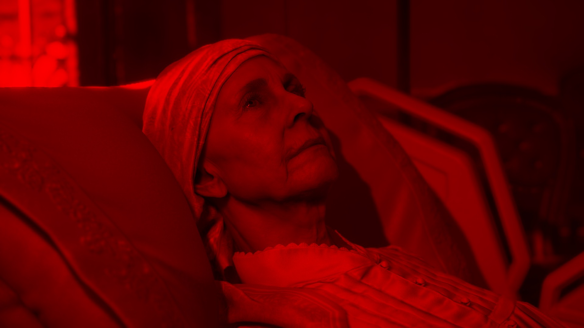
Flare Steps Example 3


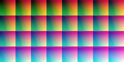

Flare Steps Example 4


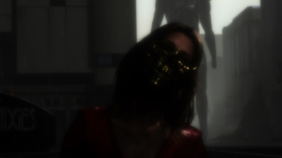


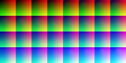
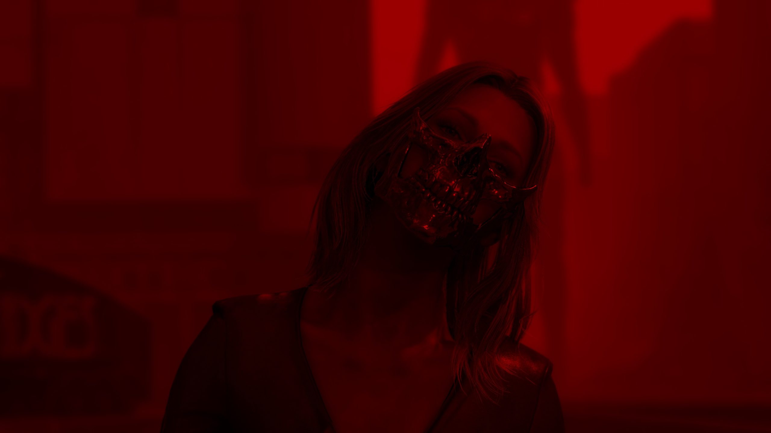
Flare Steps Example 5


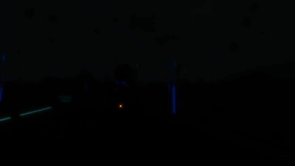


Flare Steps Example 6


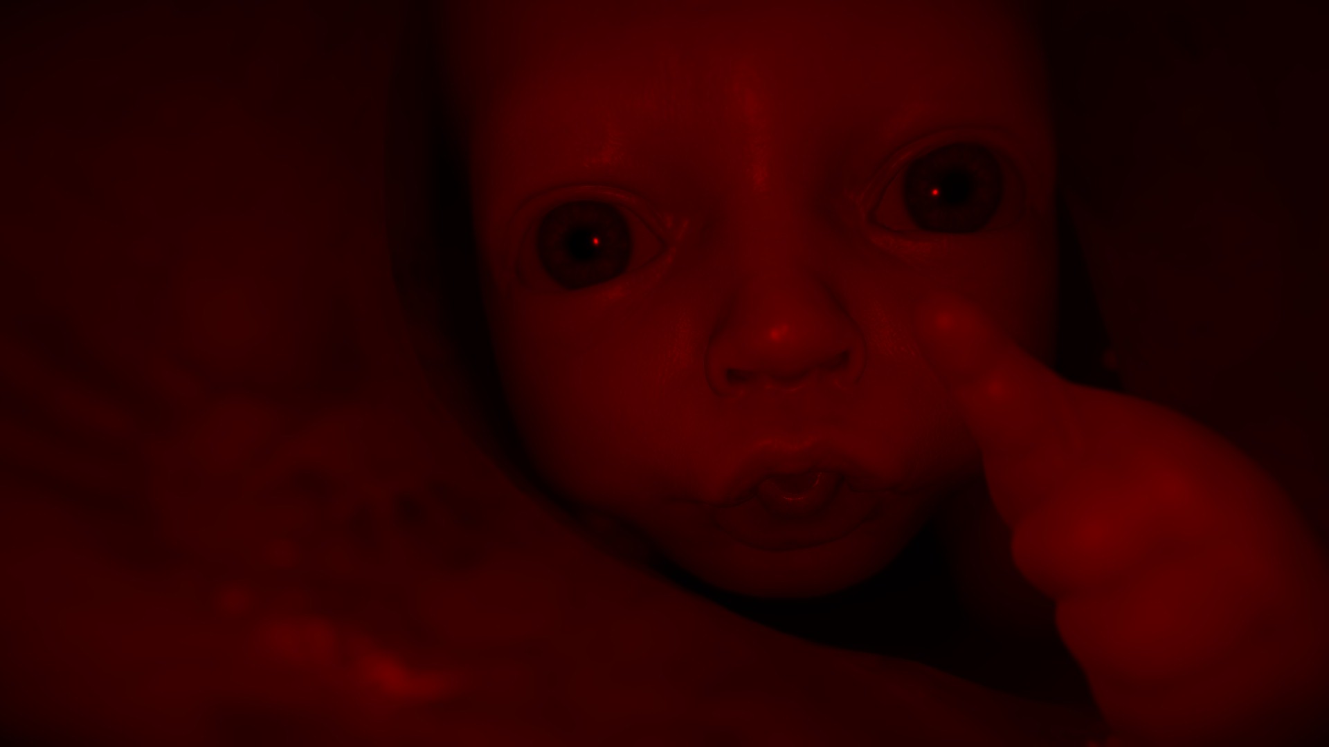
Flare Steps Example 7
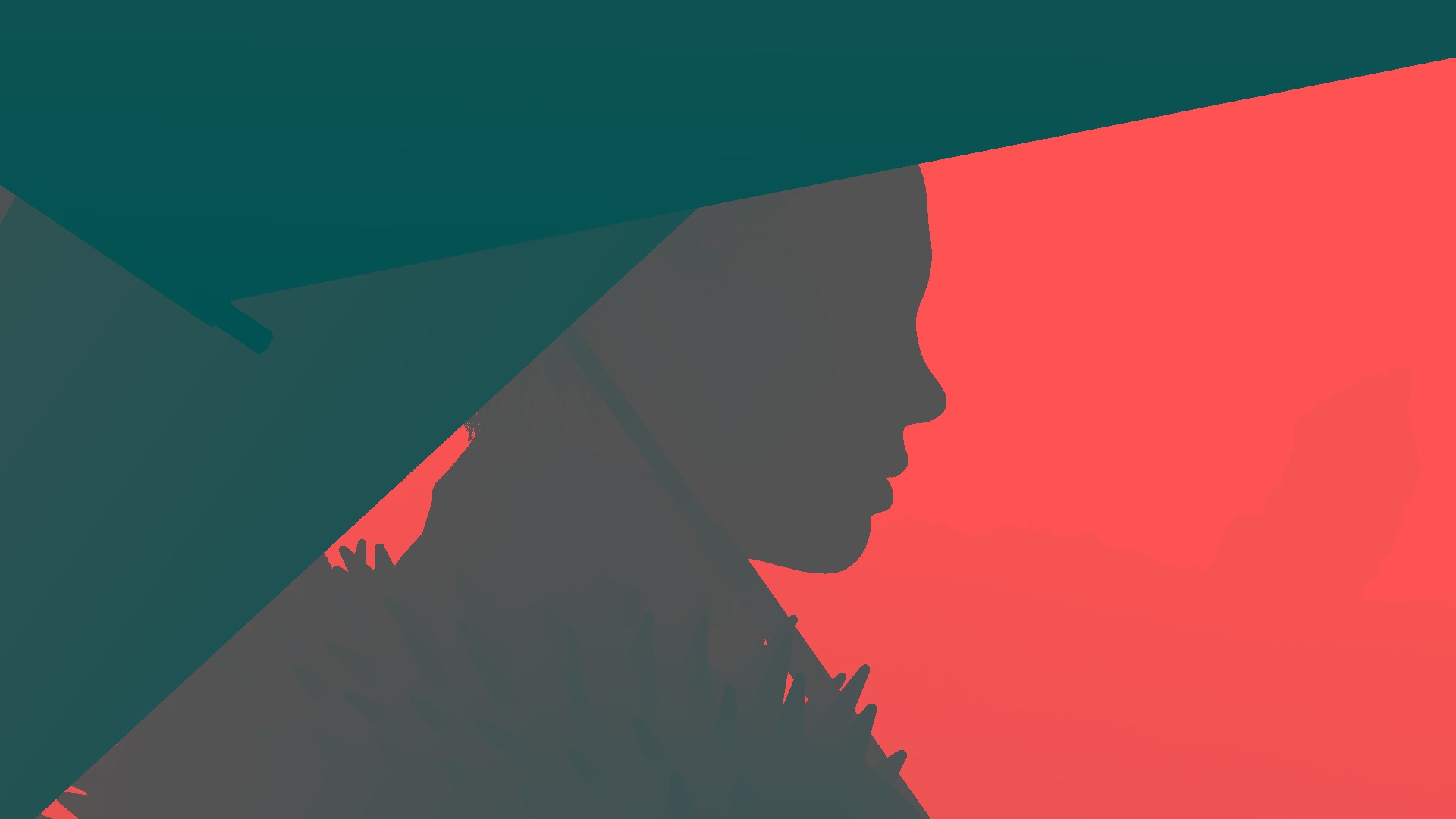
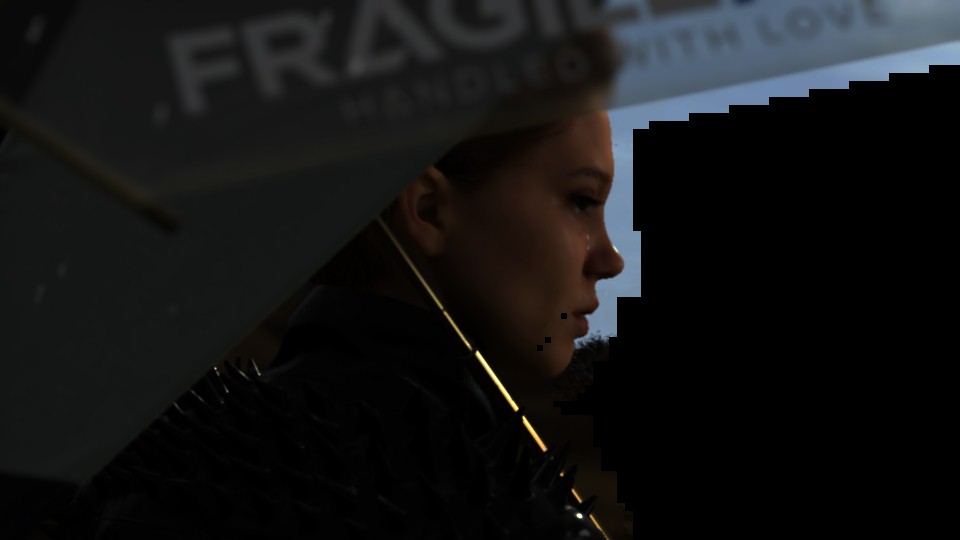
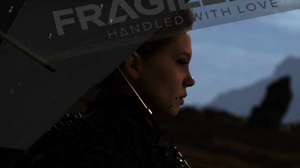


Flare Steps Example 8


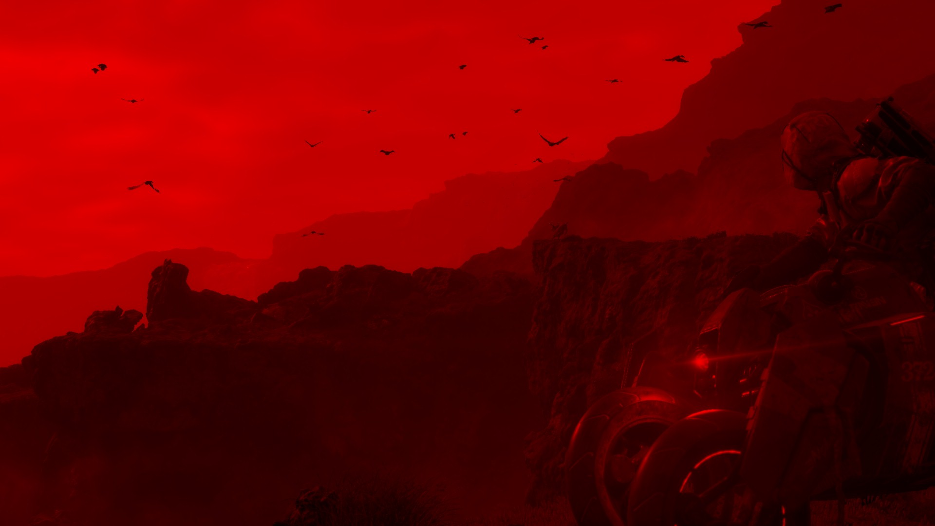
Flare Steps Example 9


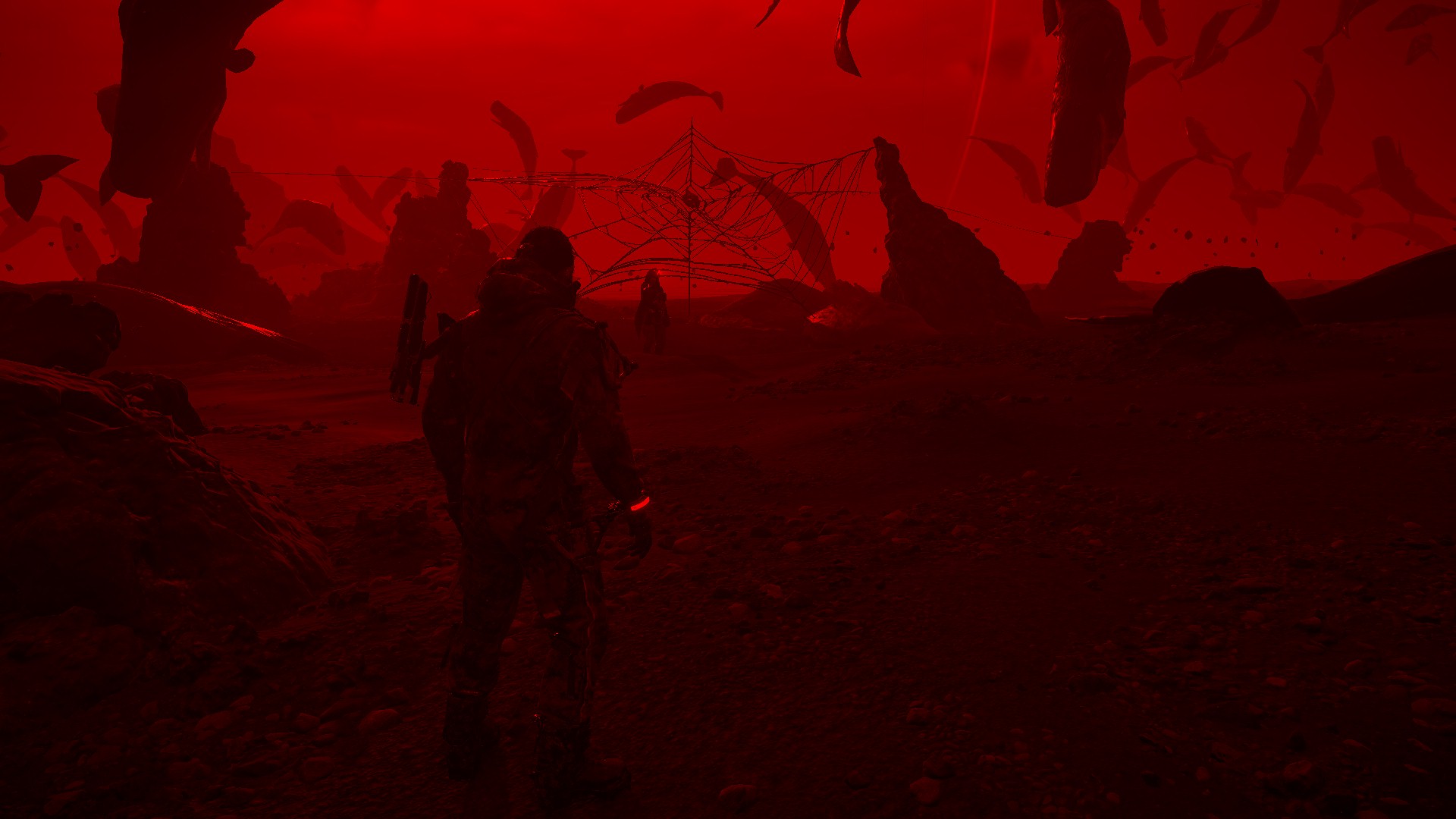
Flare Steps Example 10

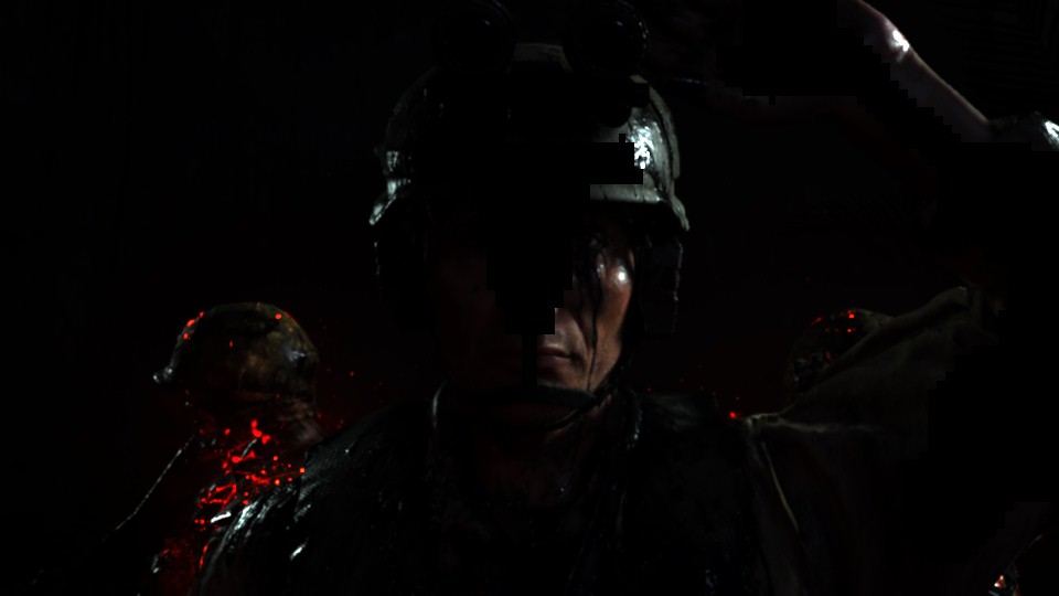


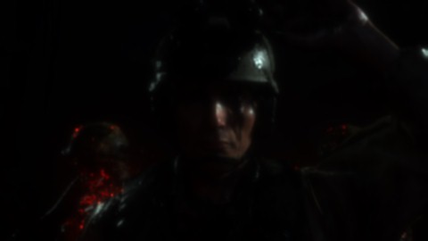


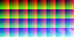
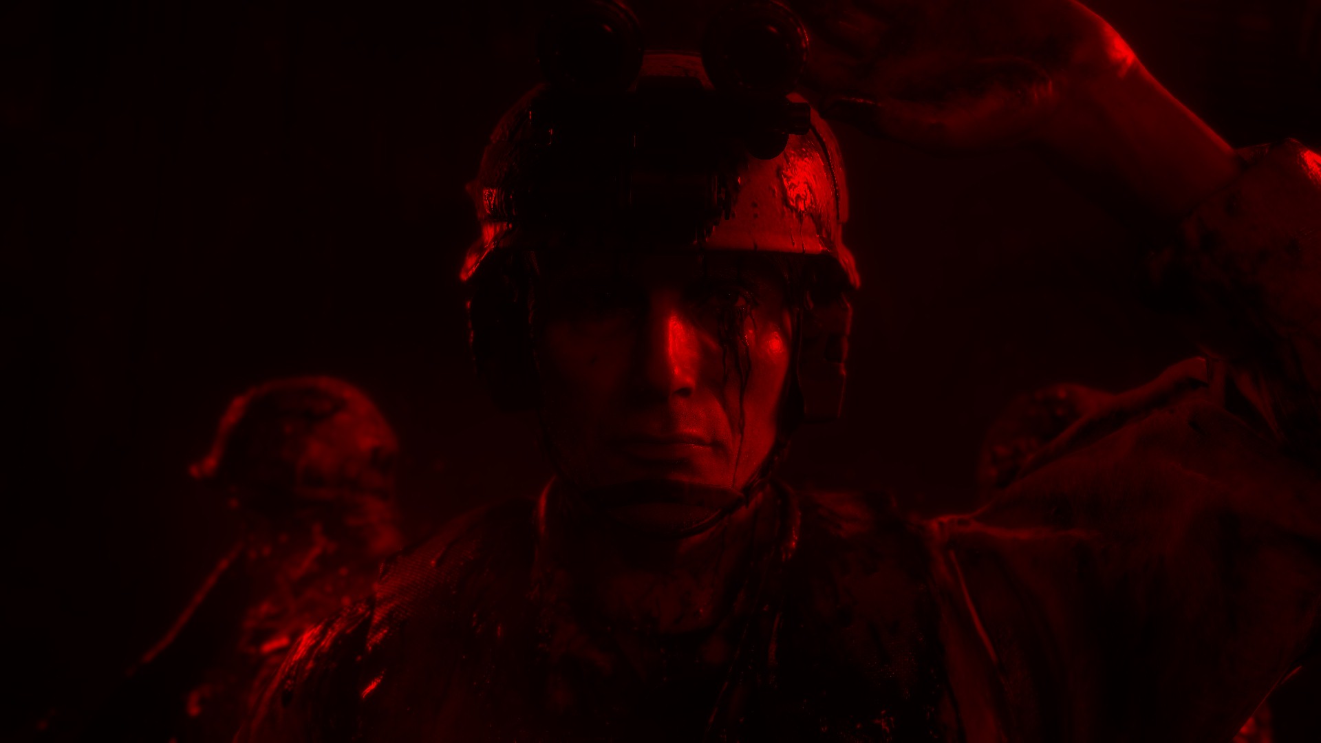
Flare Steps Example 11


Flare Steps Example 12


Anyway, for that purpose, and during this pass/shader, there are some quite interesting params passed around
Post-Process Params
struct mPostProcessParams
{
	float2 mRgb3dLookupScaleBias;
	float mLightShaftIntensity;
	float4 mLightShaftColor;
	float mDistortionIntensity;
	float mDistortionFalloffIntensity;
	float mDistortionFalloffPower0;
	float mDistortionFalloffPower1;
	float mDistortionFalloffHorizontal;
	float2 mDistortionAspectRatioMultiplier;
	float mContrastIntensity;
	float mGrainWeightScale;
	float mVignetteScale;
	float mVignetteBias;
	float4 mVignetteColor;
	float4 mExposureControl;
	float4 mHDRCompressionControl;
	float4 mHDRDebugControl;
	float4 mHDROutputControl;
	float4 mOETFSettings;
	float4 mKjpGammaSettings;
	float4 mHDRCompressionParam1;
	float4 mHDRCompressionParam2;
	float4 mHDRCompressionParam3;
	float4 mWhiteBalanceControl;
	float4 mFullResUvClamp;
	float4 mHalfResUvClamp;
	float4 mQuarterResUvClamp;
}
Post-Process DOF Params
struct mPostProcessDoFParams
{
	float4 mCoCScale;
	uint4 mTileSizeMultiplier;
}
i’ll leave just names below a heading with little notes for the major post-processing effects that gets applied here, and because of the fact that it is one shader taking the inputs and giving the output at once, it won’t be possible/easy to demonstrate how the final frame looks like after each one of the post-processors in that stack. Where in other games that we discussed earlier, you might’ve noticed that you can see the frame state after each of those effects, but here it is actually much more convenient, optimized and makes sense. So with the fact that i can see how the frame looks like after each of those steps below, but i’m super satisficed that this is the architecture behind it in Decima/DS!
1.DOF [Not Always]
Depends on if we’re running in Cinematic mode or Gameplay mode. And even in Cinematic, not all frames or cut-scenes have it.
2.Light Shafts [Not Always]
Depends on the status of the frame, and if we’ve generated Light Shafts texture earlier.
3.Lens Flare [Not Always]
Depends on the status of the frame, and if we’ve generated Lens Flares texture earlier.
4.Noise/Grain [Not Always]
Where the noise/grain parameters & texture always passed to the shader, but you will observe that noise/grain is not always present in frames. It’s case by case.
5.Color Correction
No comments, just just using the 3d lookup table, to manipulate the final mood.
i.Contrast
No comments
ii.Exposure
No comments
iii.White Balance
No comments
iv.Vignette [Not Always]
No comments
v.Distortion [Not Always]
No comments
It’s a very very rare case, such as that frame
Copy & Clear
Oh yeah…it’s been a while!
UI [Not Always]
The UI as expected, is not always in there, it is either during gameplay or menus, but not present in Cinematic moments. Here in this section, we only focus on the game UI, others types of UI will be discussed later.
Game UI
In a common fashion, UI elements is draw one by one using DrawIndexedInstanced commands (it’s important to know this note, you will know why later), in order to draw to a new empty rendertarget that is called LinearOverlay using a single font atlas and a whole lot of icon images that depends on the count and variation on the frame’s UI complexity. Nothing fancy, but also nothing very exciting!


And in action…

This type of UI is not my favorite, despite the fact that there is no reason to keep the UI in it’s own rendertarget as there is no special step to alter the UI alone. In fact, there is “late post-processing” that is applied to the entire frame including the UI, so why not painting the UI on the frame right away? Or do they do that somewhere else ?

Also, why no atlases ??
HDR + TAA
1.HDR
The technique used by Death Stranding for HDR seem to be the Hybrid Log-Gamma HDR (take it with a grain of salt), using the Luma Texture that was generated earlier by the end of the Post-Processing pass, HDR get applied to the scene. Despite the fact that HDR enabled or not or even supported by the monitor or not, the HDR step will be always exist in the frame lifetime.

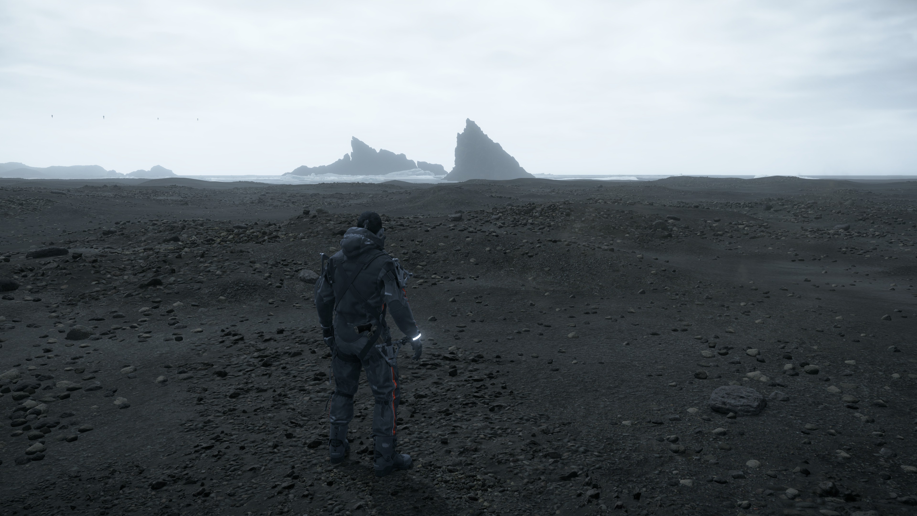
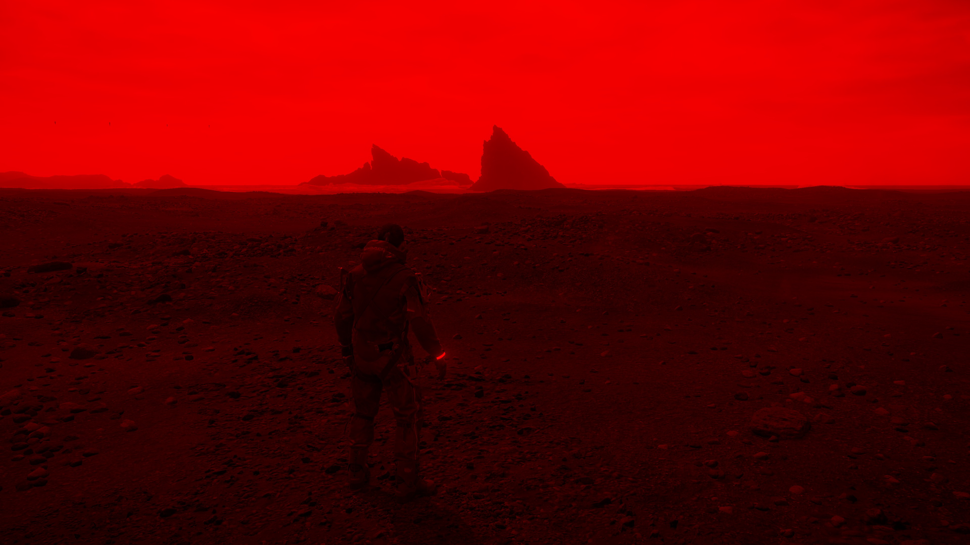

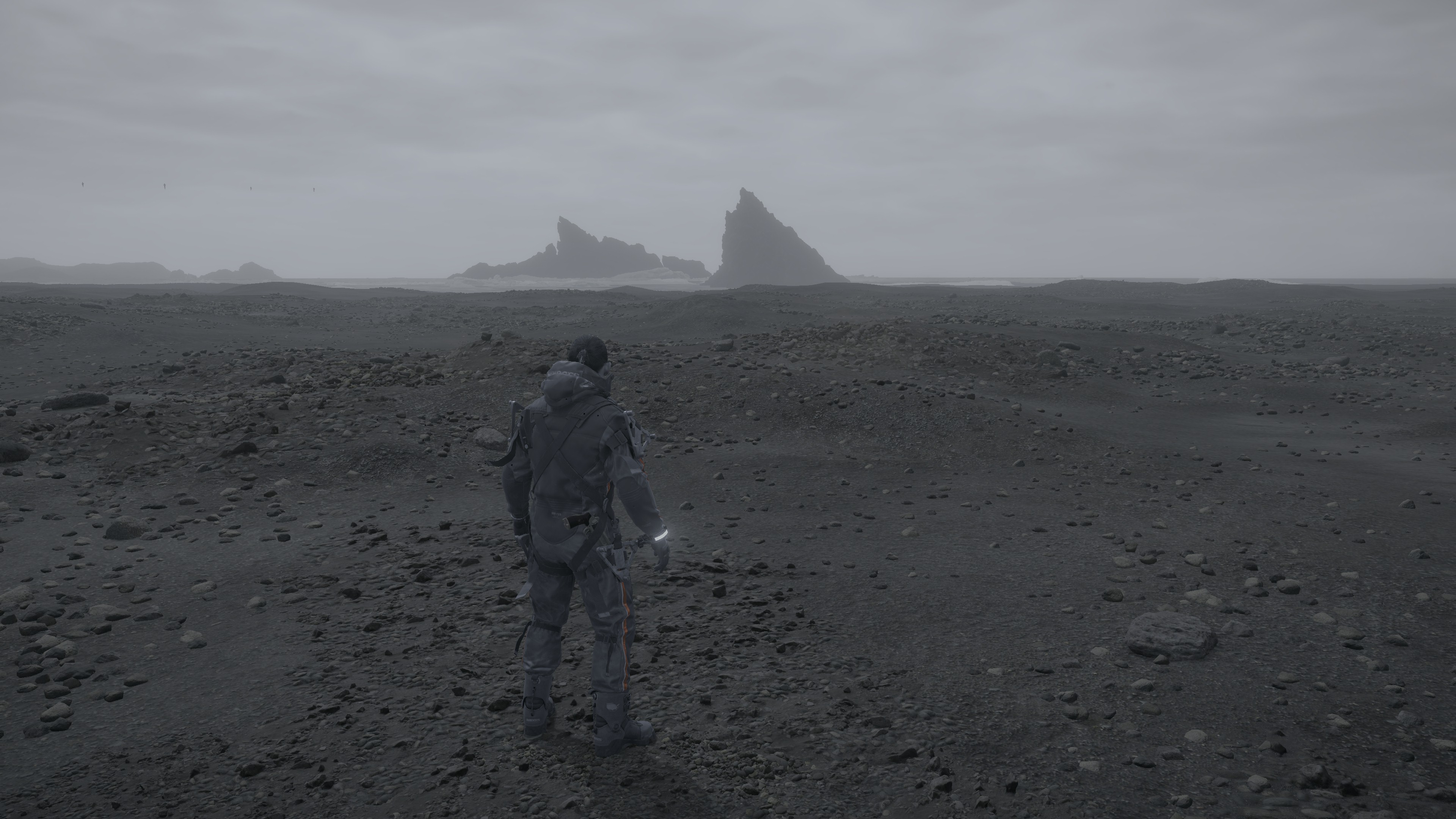

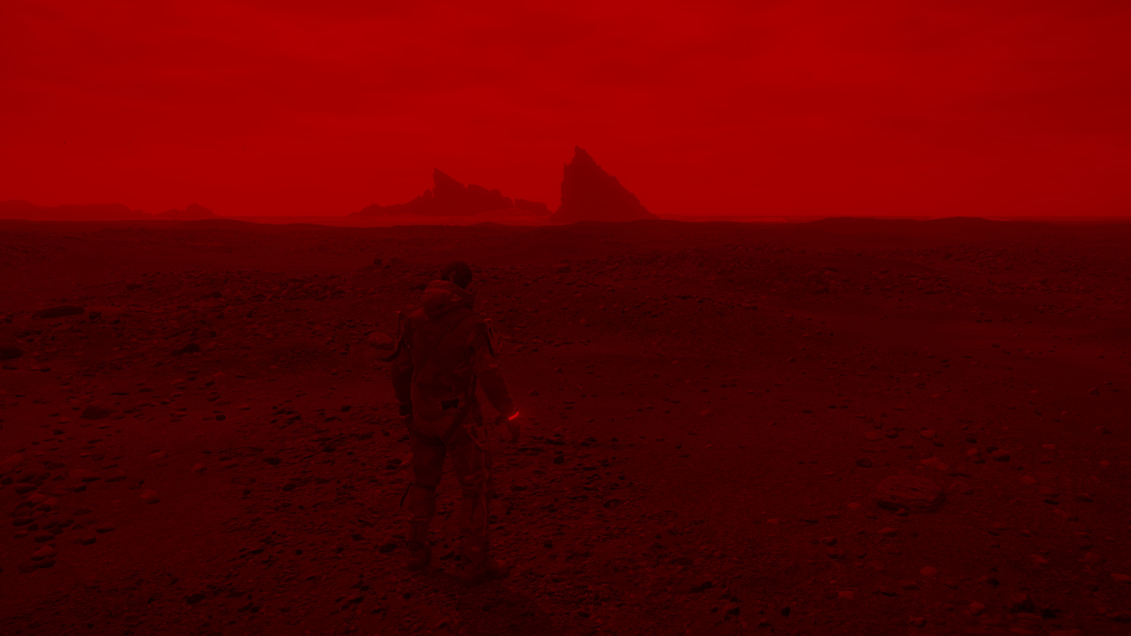
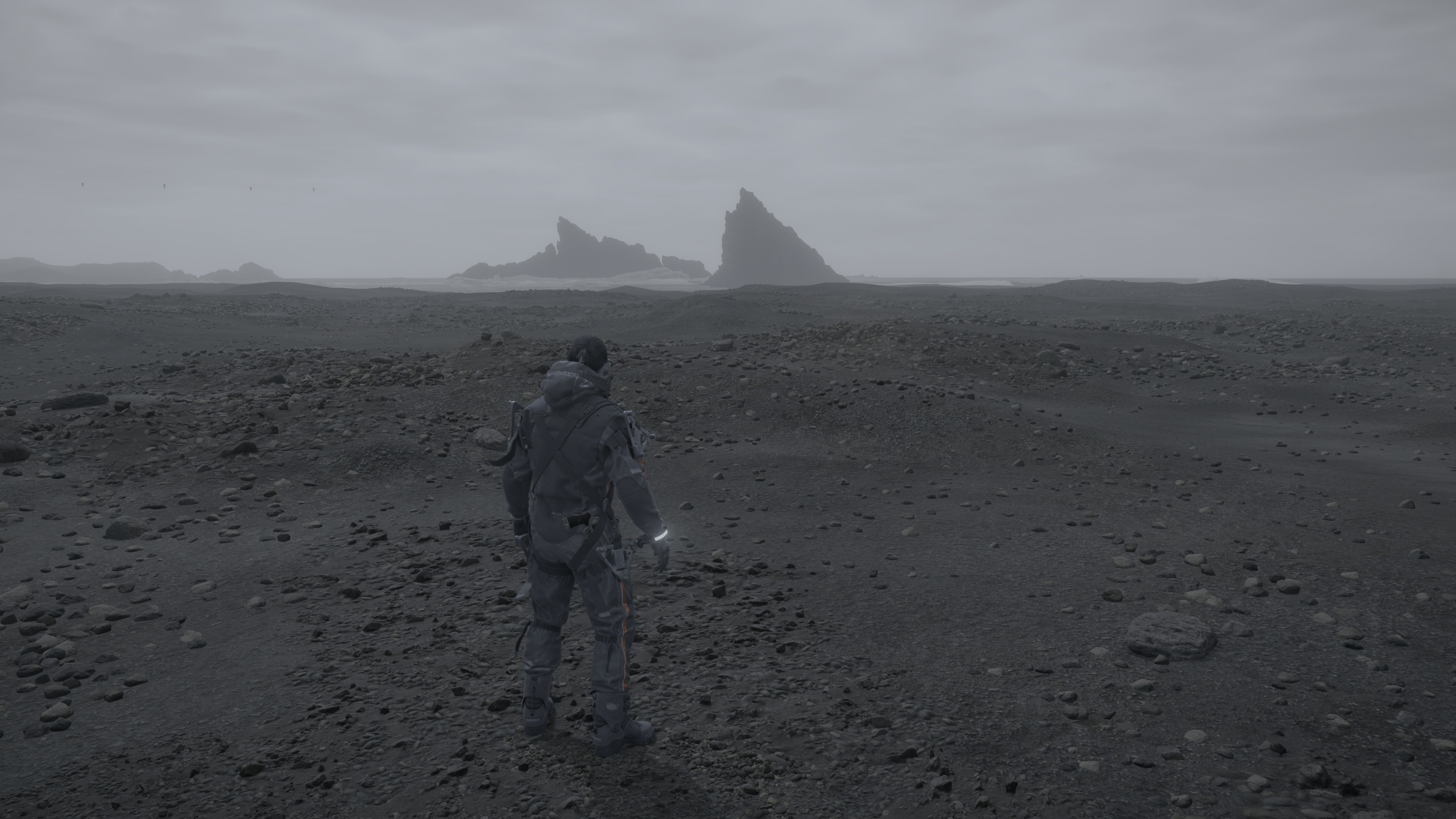
2nd row, HDR ON
All in 3840*2160
Unfortunately it may be hard to observe the difference in such image formats i used to upload here, but to give you an idea about the impact of HDR, here are below the Luma Texture been ranged in lower color range (same exact values used for both images)…
Notes for the Clumsy HDR!
– When running the Game with an HDR monitor, the game won’t enable HDR by default in the settings, implying that the game still not running with HDR mode, but with that said, it still renders in HDR!
– When enable the HDR in the settings, the game will still render HDR, which is expected, but it renders everything along the pipeline in 1/2 resolution, at my HDR capture here i was targeting 4k, and the game settings show that my “Display Resolution” is 3840*2160, but ONLY the game would present a 4k surface, but everything else during the frame’s lifetime was done as if we’re targeting 1080p.
– Disable HDR from the game settings after manually enabling it, will render normally a none-HDR even if the monitor still having HDR enabled.
– With HDR got disabled Manually, the game will still render everything in 1080p and present in 4k, where the target resolution is set to 4K!
One of the main reasons makes me tending to think a lot about the HLG HDR here, is that during the HDR step, and even if we’re targeting SDR (HDR turned OFF), the game still renders to RGB10A2_UNORM just right away before handling it to the present surface RGBA8_UNORM. When working with HLG HDR, the linear scene lights data will be converted into a nonlinear data that is suitable for the RGB10A2_UNORM.
If you are into some interesting findings & details about the HDR implementation of Death Stranding, i would recommend you this few minutes read by EvilBoris (it’s not very technical or anything, but it has interesting observations).
And believe it or not, the HDR frame capture is ~400 mb smaller than none-HDR capture : ) if i’m not liking HDR because of the vivid delivery, i may consider liking it because of that frame capture size!
2.Temporal AA
Just temporal AA as part of the HDR scene output, you can observe the difference between frames, specially in shiny pixels, take this big strands spider web alike as an example


TAA Params
struct taaParams
{
	float4 mAAParams;
	float4 mTextureParams;
}
UI Composite + Post Processing [Not Always]
After the HDR phase, regardless enabled or not, the output get composited with the UI output (the Linear Overlay rendertarget), in order to result not only the final frame output that will be presented shortly (with a format change), but also a new rendertarget for a copy of the current frame to be kept in memory for the next frame, to be the next (previous/history frame)


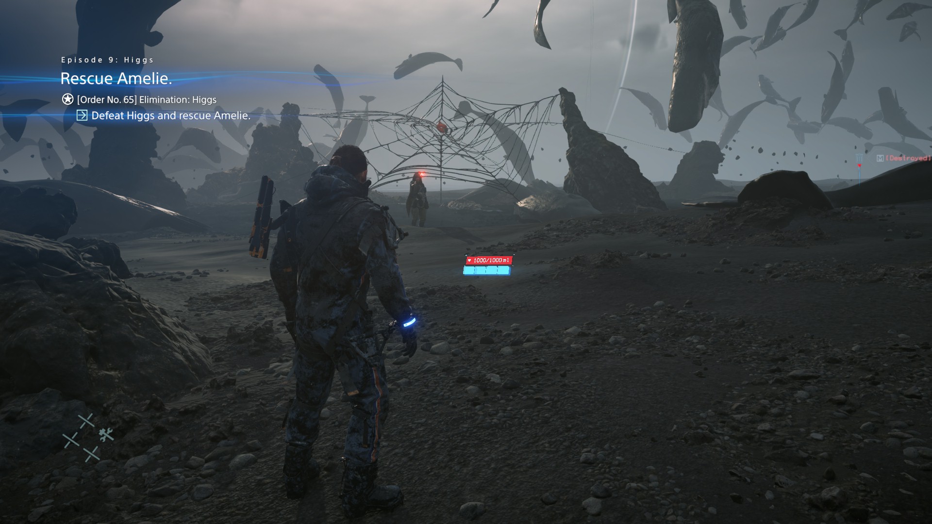

Late Post-Processing (Tone Mapping/Gamma Correction)
Just one last step to modify the current image and tone map it correctly, nothing fancy to show here, as this step happens during the UI composite step. So while compositing the UI to the frame, the late post-processing happens to the in HDR scene before the UI get stamped on it, and this is why i was not sold to the idea of painting the UI into empty render target and then composite it, where it made more sense to paint the UI right away into the HDR frame, and then apply that late post processing, that would be much more simpler, and less complexity in the render graph.
Post-Process Params
struct PostProcessParams
{
	float4 mUVScaleBias;
	float4 mParams;
	float4 mOETFSettings;
	float4 mKjpGammaSettings;
	float4 mNewHistoryUVScale;
}
Present
Final image presented in R8G8B8A8_UNORM when SDR or R10G10B10A2_UNORM when HDR with the final target resolution of 1920*1080, or 3840*2160 as those were my only test resolutions.
And with all that previous knowledge in mind, i would like to withdraw my Compute Dispatches meme from Death Stranding (and Decima), and replace it with a new and well deserved animated one!

Life of a Frame [Rendering Graph]
Now after we got a clear idea bout what are the major stops at the graphics & compute queues in the life of a Death Stranding (Decima) frame, it’s the time to reconstruct the entire frame’s rendering pipeline/graph (for a yet another what i assume typical/golden frame[s] that possibly include as mush as possible of the features) and have a pseudo visual diagram for a frame’s journey.
Where i used to do in Behind The Pretty Frames a full frame re-construction video[s] as (and i quote from previous article) “i do love look at such video or steps, and see how long it takes me with my normal average human processing speed to see every step”. But this time i wanted to go with a little different format….an actual Rendering Graph/Diagram.
WIP – to be uploaded soon
Engine General Observations
Menus UI
Menus most of the time is quite different, there is no actual frame rendered, in fact, there is kinda snapshot or copy kept of the last frame’s HDR+Luma+MotionVectors pre opening the menu, this is used as the target to composite to. So there is no actual “3d” around. And the rest is similar to regular UI drawing, just step by step, one by one, into a side rendertarget, but the major difference from game UI, that here drawing happens as DrawInstanced, not as DrawIndexedInstanced as the game UI.

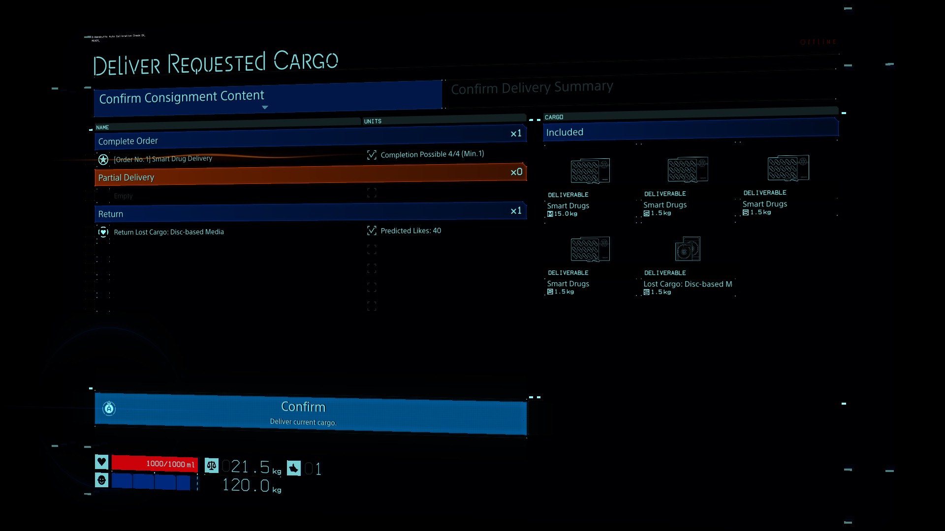
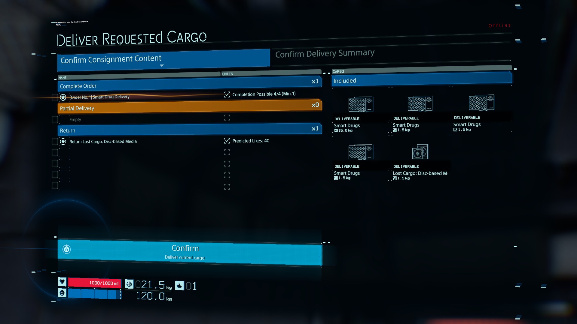
and in action….

World Map
So far we’ve been addressing many UI styles in DS, like Game UI, In Level 3D UI, Menus UI… But yet, Death Stranding have one more (and the most interesting one) type of UI, which is the World Map. This one is really cool, even thought it is not something you might see a lot during playtime, and even if it might be expected how it works, but i decided to dive into it, because i felt it might be different somehow from everything else (everything else similar in other games, and everything else in Death Stranding itself) because the entire frame is dedicated to UI only with almost zero influence from the gameplay 3d items. Here how it works in separate (and hopefully clear) steps
1.Keep Last Known Game Frame
In a similar fashion to the menus UI, the last frame seen before the UI start rendering is kept aside (along side it’s Luma and Motion Vectors), as there is no real game world been processed or rendered in the background such as in some other games. So, keeping a snapshot of some data is the approach here.
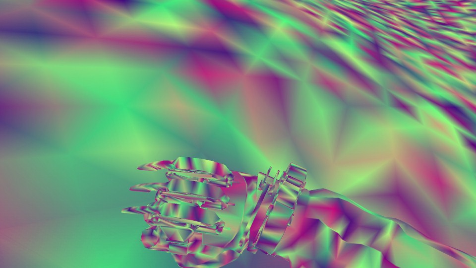
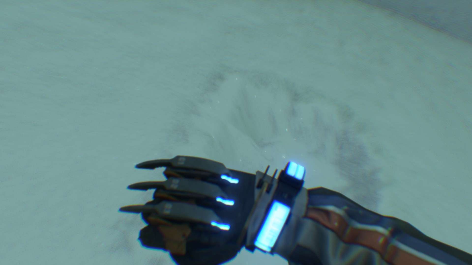
2.Map Renderpass
In this 1st dedicated renderpass, pretty much everything “map” related get painted step by step with DrawInstanced cmds, it takes quite a while, as the map is really heavy as you will see below.
i.2D Map Base
Step by step laying the foundation of the map, using a pre-rendered images that are captured from the terrain. You can think about it is, as if the entire world map is split into pieces that each is 1024*1024, when you open the map, the player player get located, and hence loading the few pieces around them.
So using those
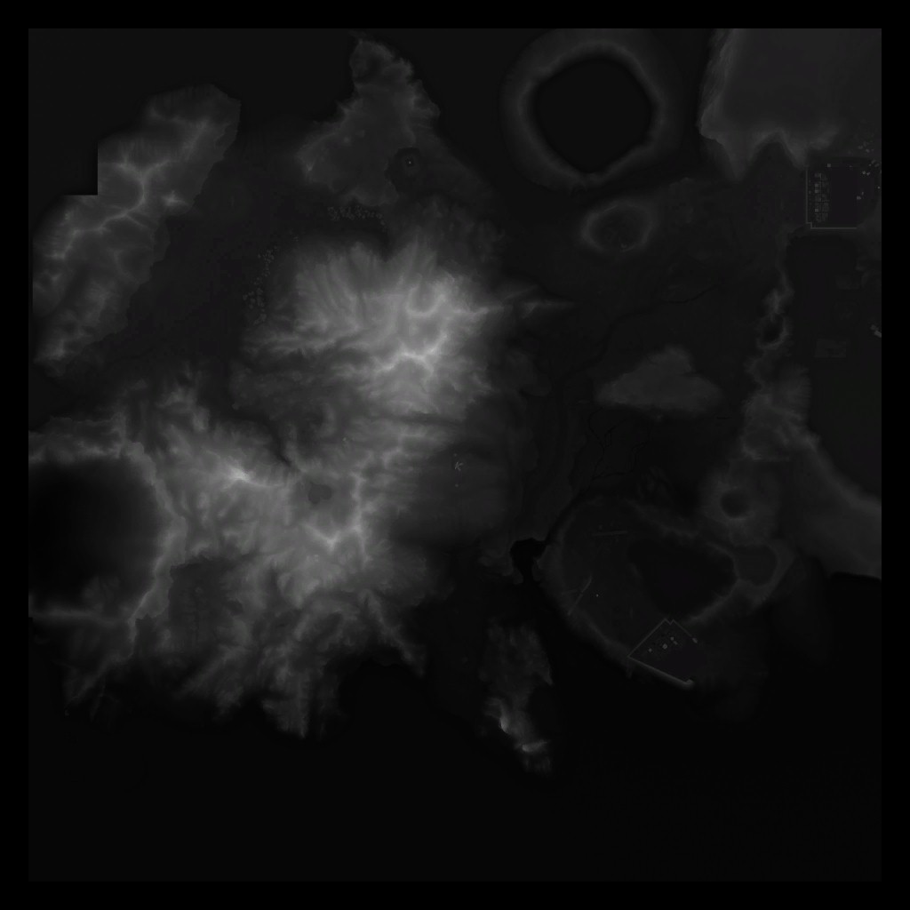
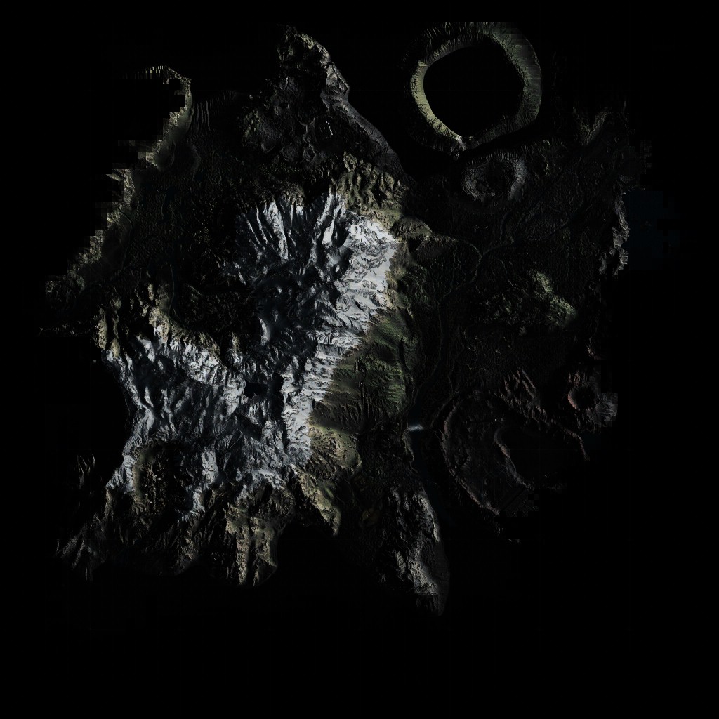
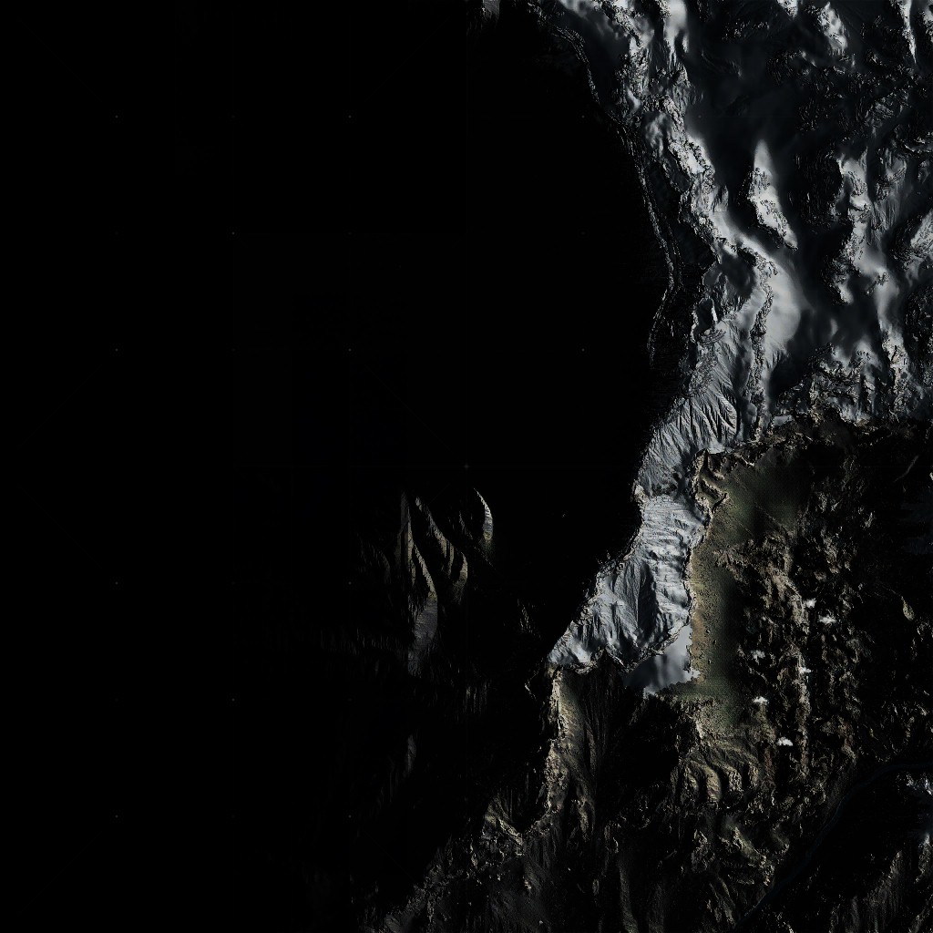
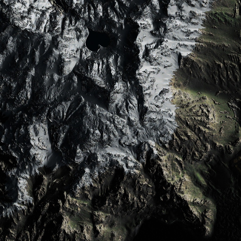
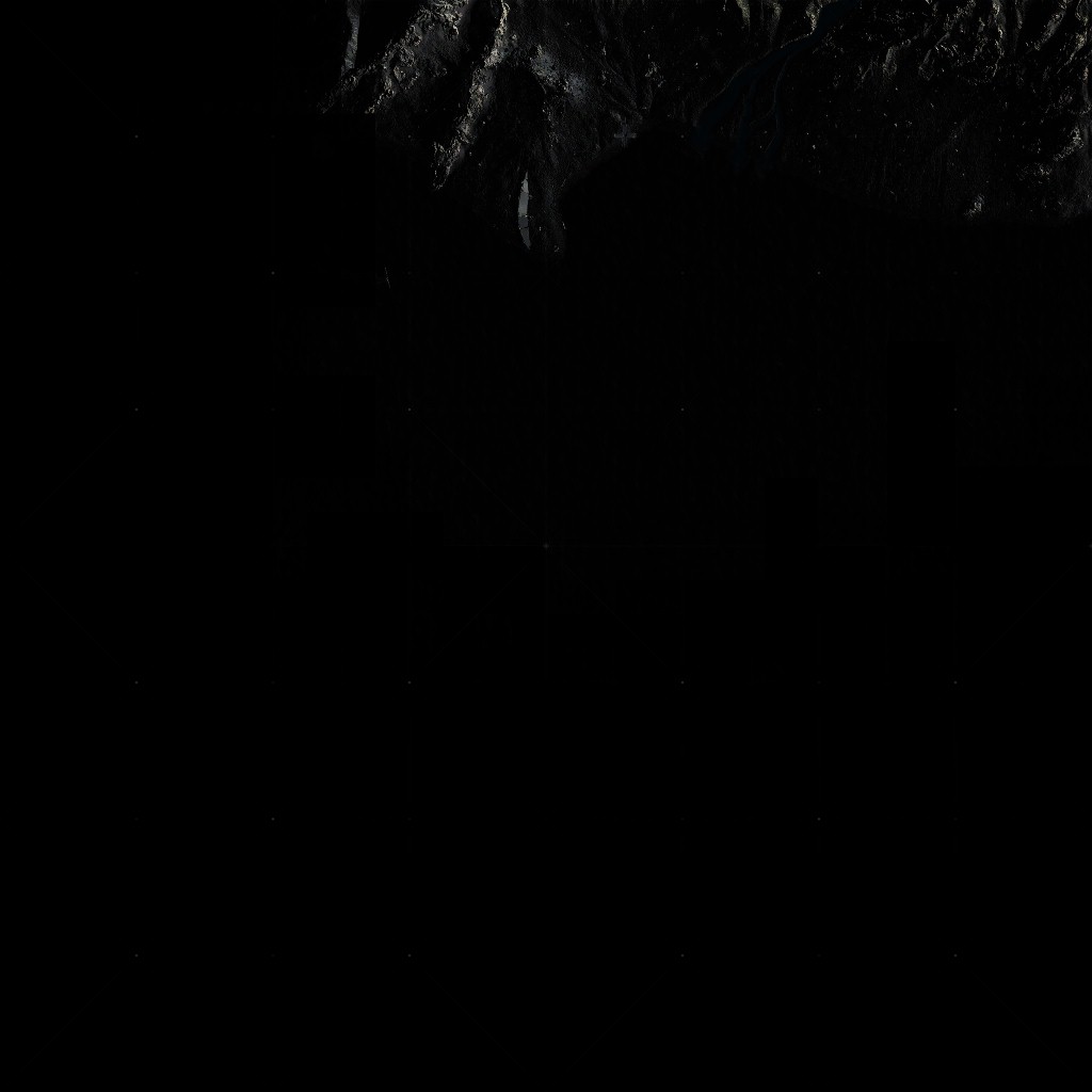
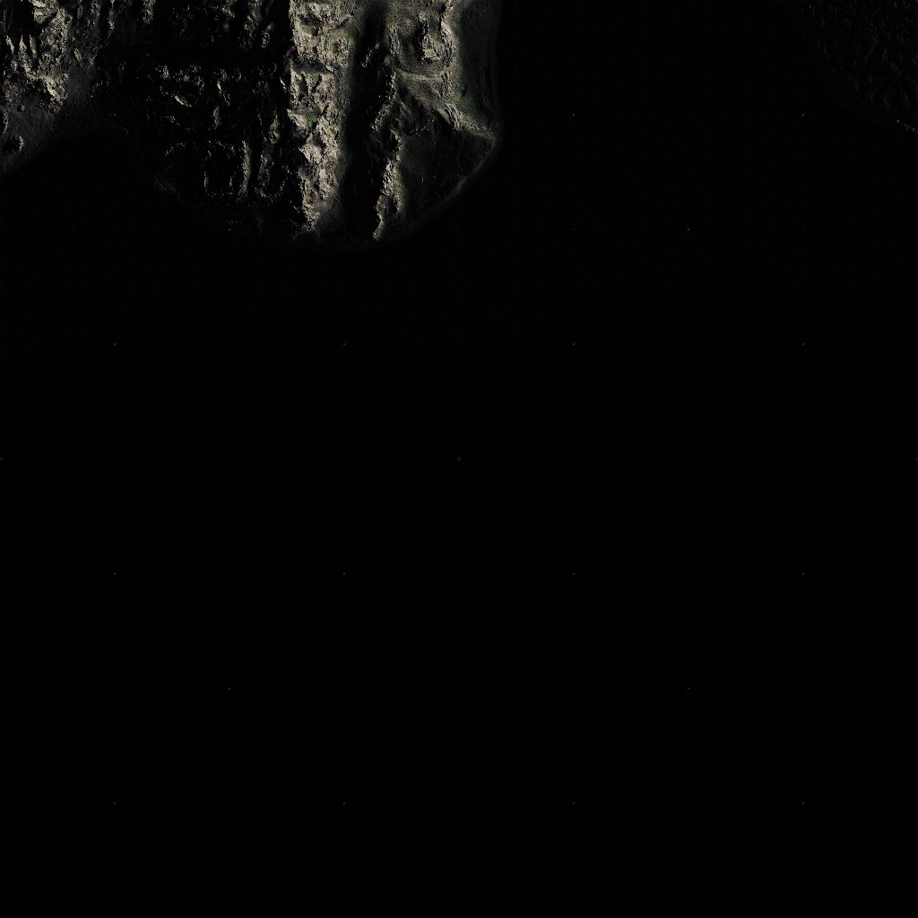
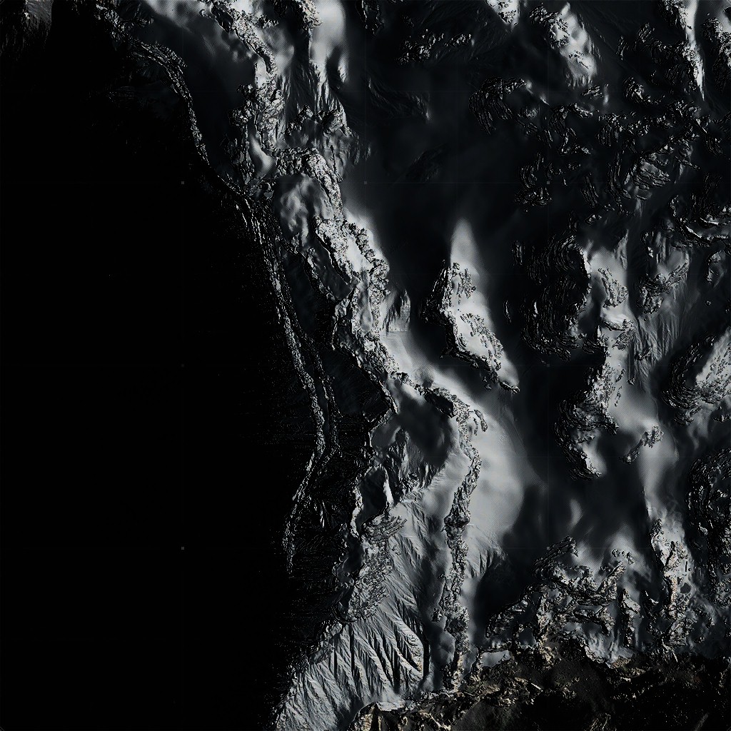
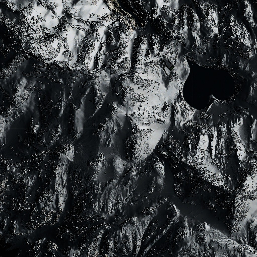
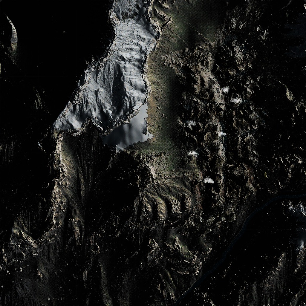
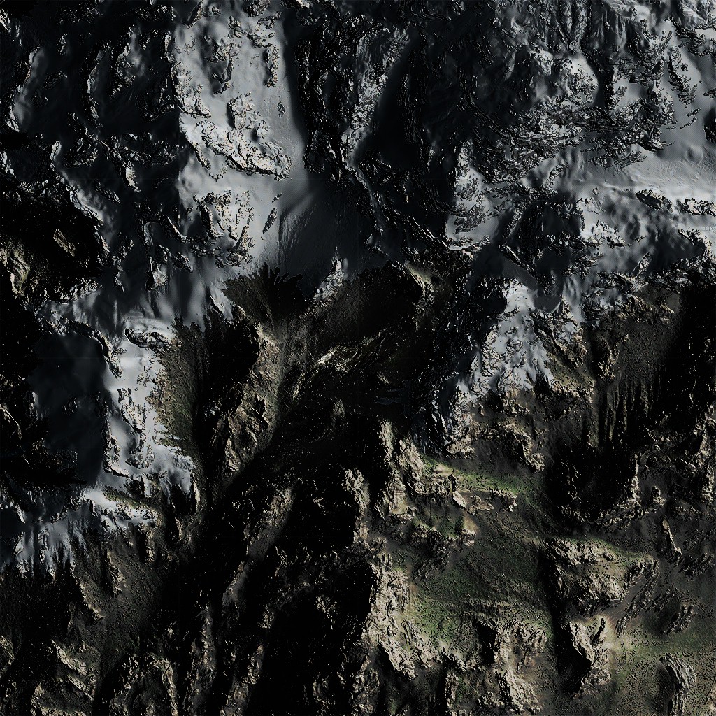
In order to end up with this map
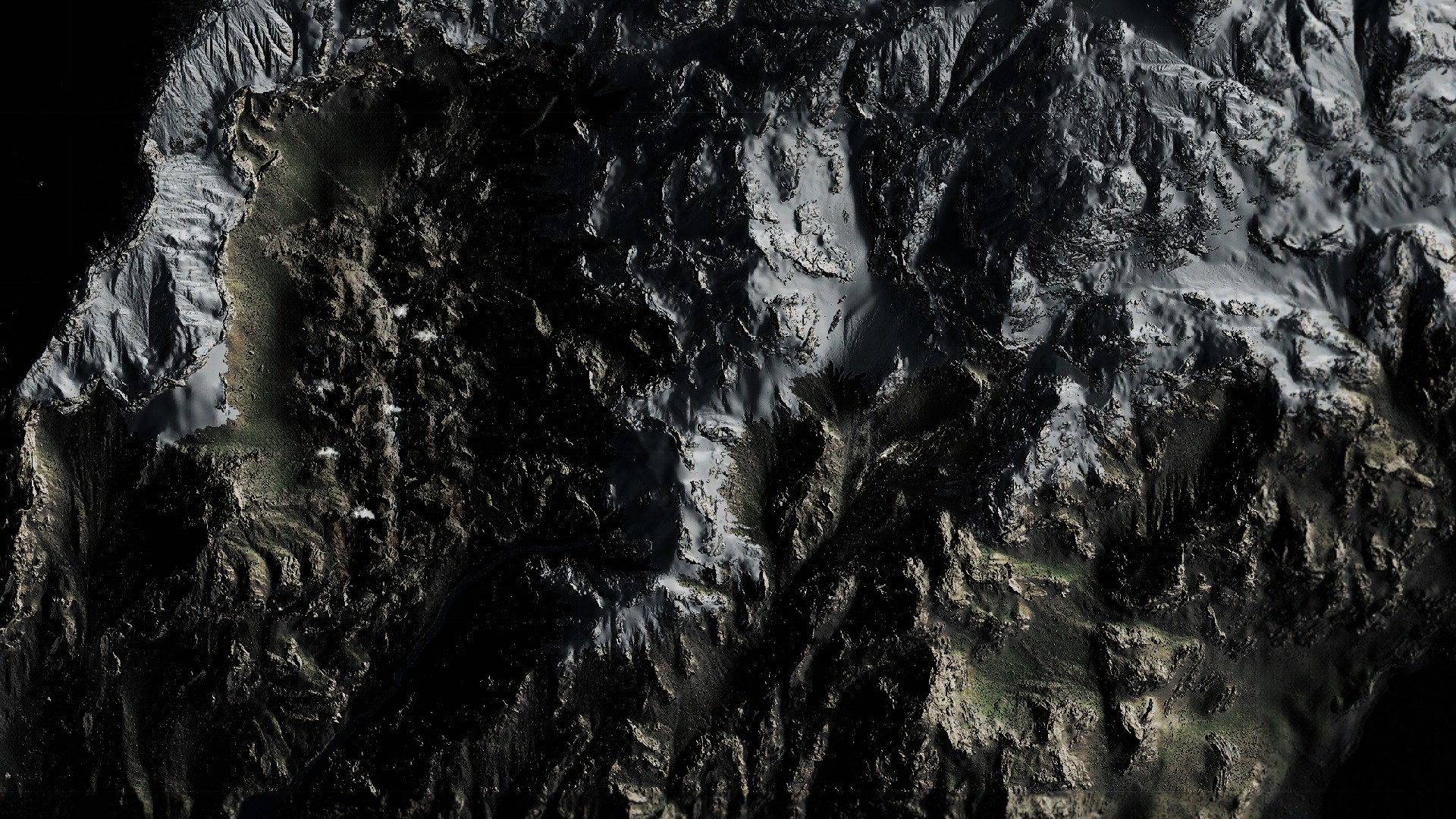
ii.Grid
This is one of the longest and most tedious steps, here the grid behind the map, get painted line by line, vesical lines first, and then horizontal lines. It’s one by one, and it’s about (not exactly) 280 vertically and 110 horizontally (there is actually lines that are less visible between the main lines o_O). The thing is, this could’ve been replaced with a single mesh, or even better, a single grid texture!
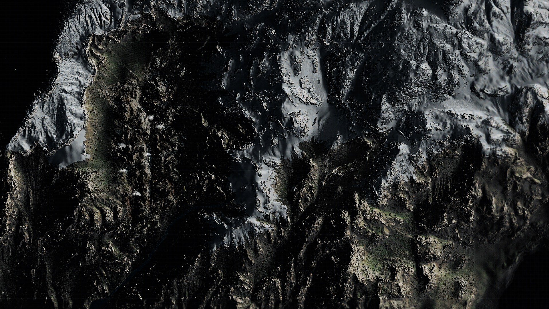
iii.Road Network
Just drawing some lines that represents roads. Nothing fancy.

iv.Icons Shadows
Again, using a group of icons, and i don’t know why not atlases, to draw one by one the icons with solid black for reach icon that will be placed on the map. This is basically exactly as if painting the icons, but just fill in black color.
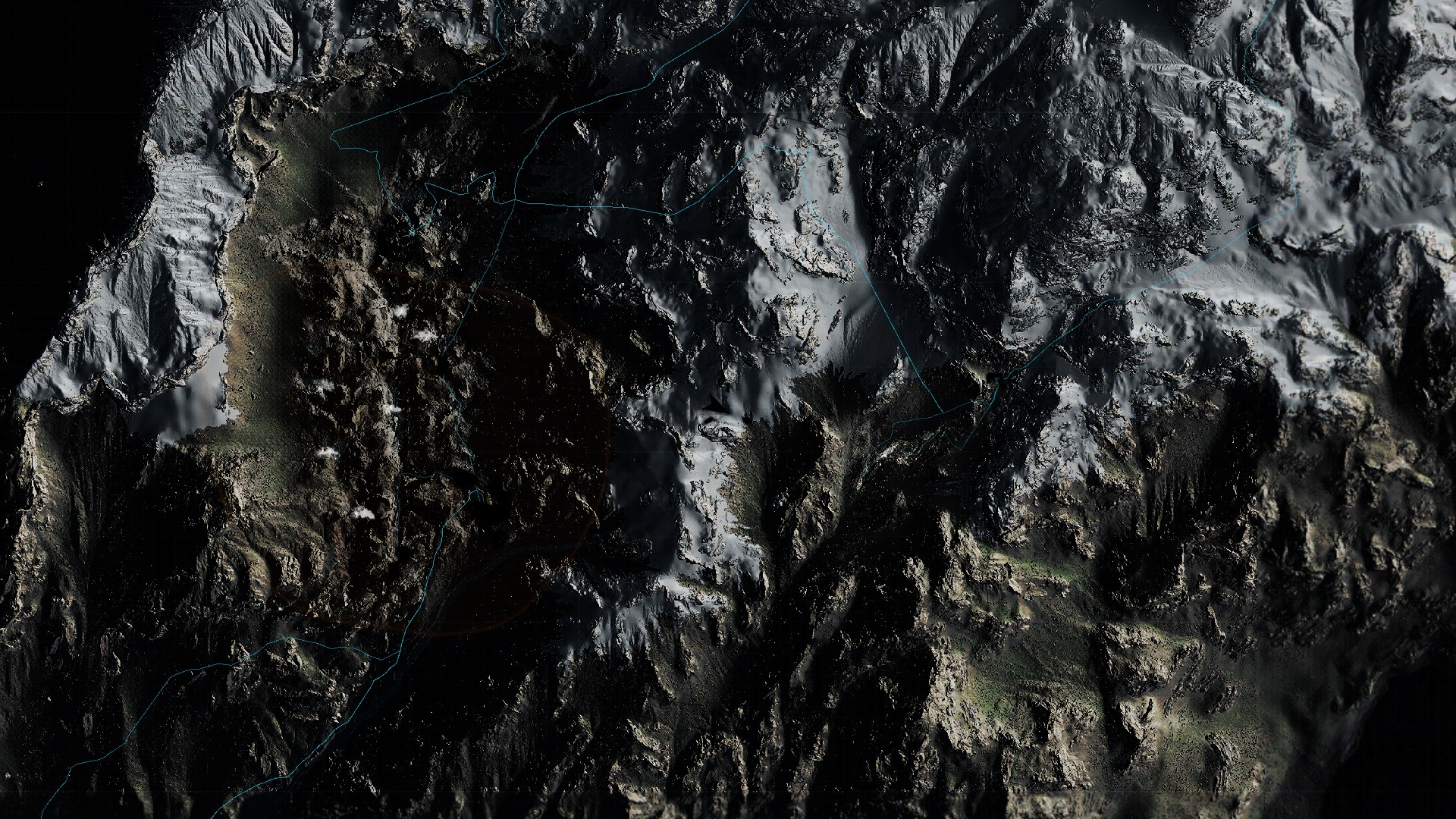
3.Interface Renderpass
This is the 2nd and last dedicated renderpass, here everything that is not map, but more of game UI, Options, Menus, or Info get painted. It is painted at the exact same way as the previous renderpass.
i.Tilt
Now, keeping in mind that the 3d map works as a form of hologram that is showing up from Sam’s arm gadget (something like that), so the map need to feel like as part of the game world (which is not exist), need to feels more like a 3d space thing, not a map sticking to the HUD in the 2d space. And hence, comes the tilting step, where this rendertarget surface gets some “skew”, in order to feel more in the 3d space. And because that would makes the plane looks “very flat”, there is some height map texture that is used to help in selling that “depth” feeling, and even used the same texture to apply some “fading”.

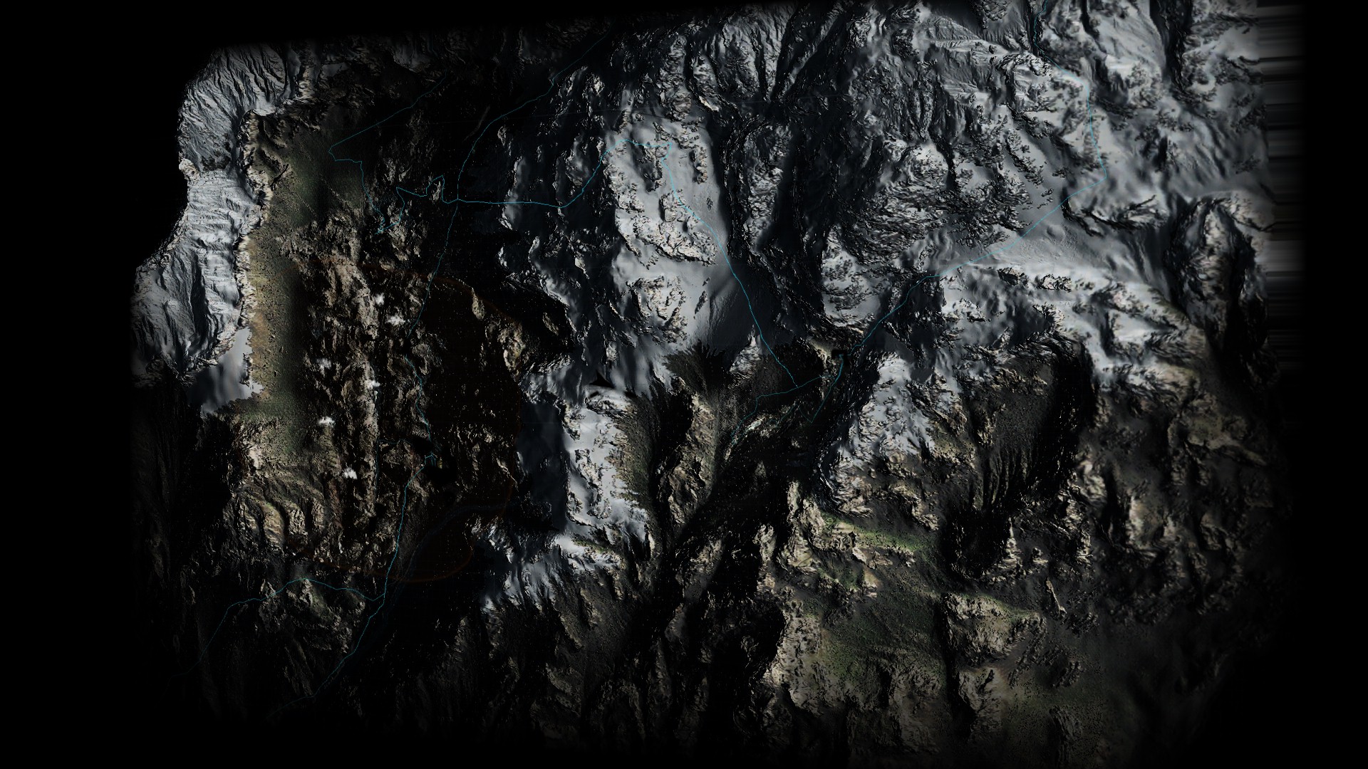
And if it is not clear what it really the difference between the in & out rendertarget states, may be a gif will sell it more to you…
i personally found that this tilting is very interesting design choice with a very neat implementation at graphics side. It makes me as player, every time i open the map, i just toy with the map before i actually use the map for whatever reason i needed it for! 😡
ii.Mask
Using a simple masking texture, in full screen, just to make the map looks more digital or futuristic technology

iii.Icons
Now remember in the previous renderpass, when there were some shadows were painted by the end of the pass, that will represent shadows for icons. Now comes the time to stamp those icons on the map, with a slight offset from the shadows, so it feels like icons hovering over the map. Of course during this phase, there are other icons get painted too that has no shadows, such as navigation arrows & directions icons.
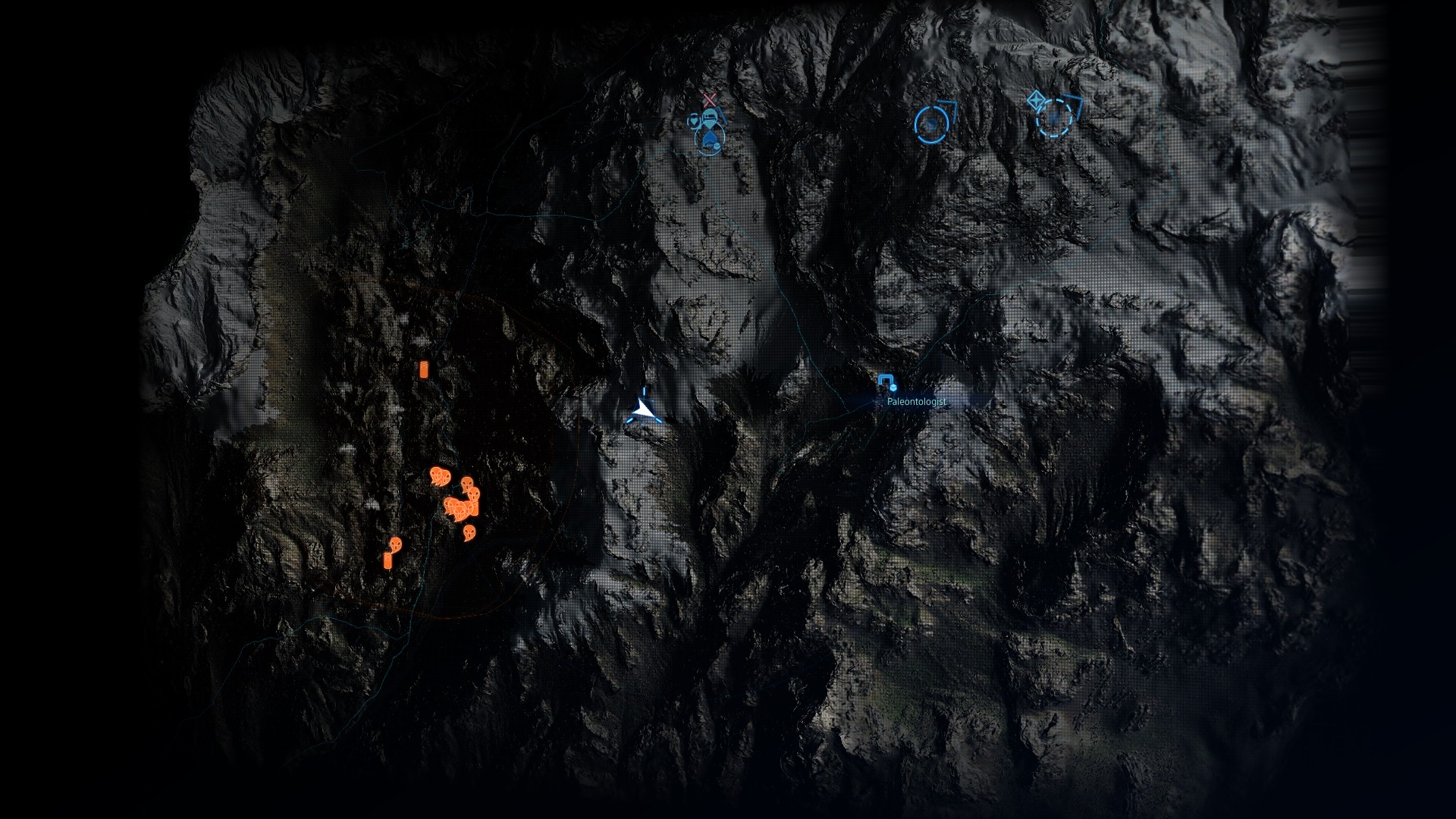
iv.Game UI
Finally, and to the end of the renderpass (which is quite a lot of time with ~2000 drawcalls), keeps painting text & other UI elements using font atlas and penalty of individual textures (exact same as menus UI) in order to come up with the final map

And to put all the work done in those 2 renderpasses in action, here is how detailed (and very long) the process is (Yes, 10 minutes worth of drawcalls)
4.Send to Composite
Now with everything ready, the rest of the frame is just like any other frame, just send the Linear Overlay (the UI rendertarget) to the UI composite step (same as discussed earlier with regular gameplay UI), so the game composite the map with the last game frame, do the late post-processing and send to present.
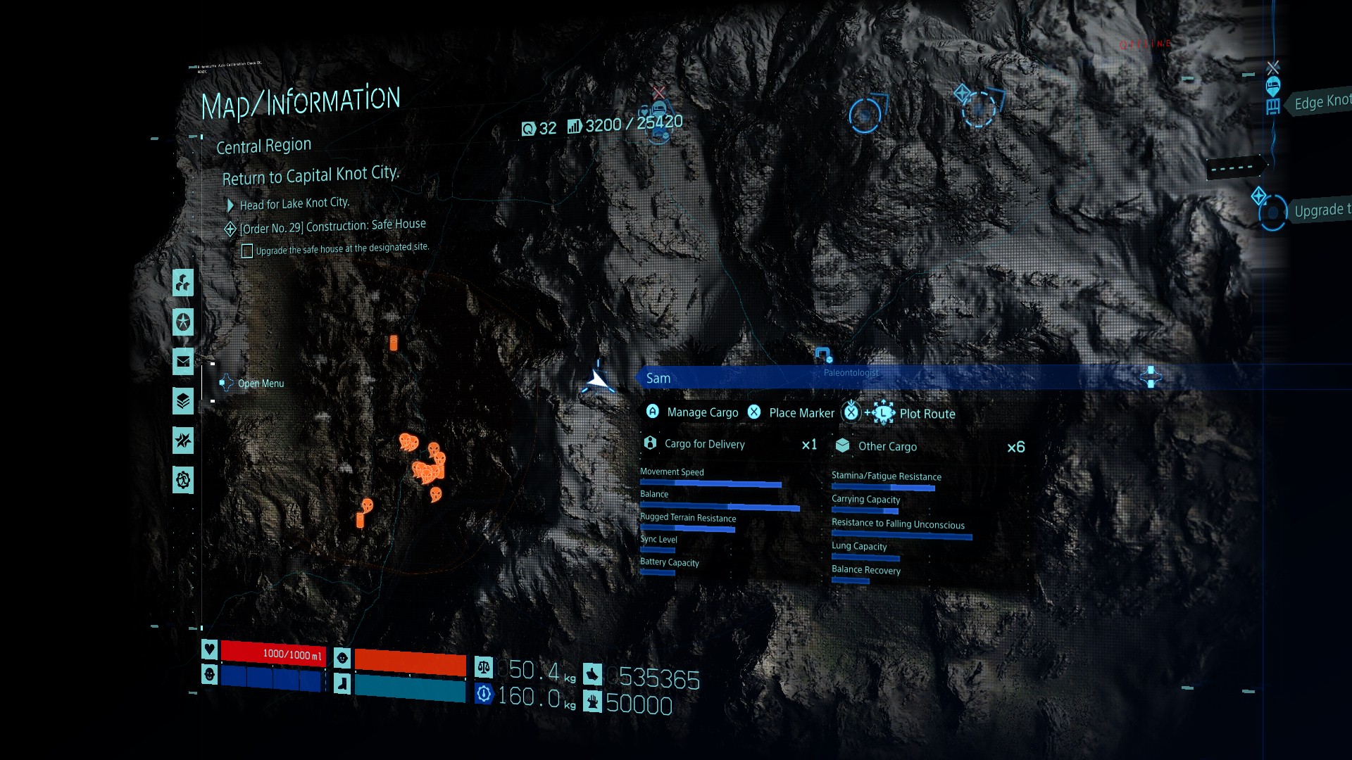
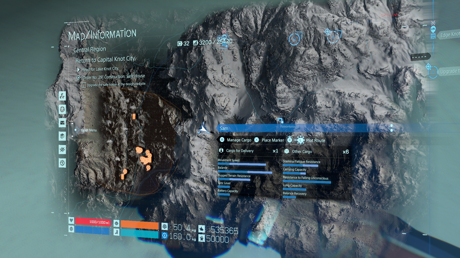
And that’s it!
If you are not familiar with the game altogether, or not sure about that map, or not remembering it’s details from your playtime, you can have a look at this quick toying around the map video. You can observe how amazing the height map impacts the map rendering, you can see the tilting & why this step of screenspace to worldspace needed, and you can hopefully notice the freeze gameplay frame when entering & exiting the map.
i liked that map, and i liked the attention to detials….it is well made (despite some optimization facts indeed).
Culling
I remember few years ago when Horizon 1 released and the GDC talks started to kick-in. In one of the talks or in an article or reddit post (can’t recall the exact occasion behind the initial show for that footage) Guerrilla showed culling (Frustum Culling to be specific) footage, and it went viral. For many gamers and YT channels, this seemed like black magic, but for common game developers we knew it’s nothing new…

Umbra, custom solutions and such been exist for decades, oh man even free engines like Unity had out-of-the-box Umbra since the early versions (Unity 2.x) which was years & years before Horizon. Anyways, during that time, the impression been given about Decima that it has amazing culling capabilities in order to optimize the games built with it to the maximum performance. Not to mention the Killzone and PS3 ear articles that made it’s way to the public audience as a result to that gif, all that was still giving the impression that Decima is culling the heck of the scene in multiple ways like a boss. BUT…and this is a big BUT, while digging (let’s compare to RE again) i’ve noticed that no earlier culling (occlusion culling to be clear, perhaps compute based culling as RE) is taking place, and during the GBuffer drawing, a whole lot of meshes (large, small,…and all sizes) are get drawn “BEHIND” other meshes, or at least evaluated for draw, not just skipped in culling stage.
Of course Decima/Guerrilla/KJP got some pretty foliage & grass tech that is worth being proud of, but why would you draw all that hidden foliage if not seen?!
Of course, those are not the only thing drawn behind other meshes in that frame, but i wanted to keep the gif duration manageable!
And with that observation, so what are the actual efficiency of those streaming & culling steps in the compute queue that been mentioned very early in the article at the start of any frame.
Automatic UVs
well, multiple meshes around the game seem to not be UVed manually and with care, and it just used auto-UV generation, which is quite strange artistic choice. I know automatic UVs could be very very fast & productive but at the same time it can increase the seams in texturing…But could it be “great” choice for “hardsurface”…!
Copy & Clear
For the 1st time in those articles you would notice me listing the Copy & Clear passes, all of them, and this never been the case before, because there weren’t much in fact! The huge amount of Copy & Clear passes in that game/engine here comparing to not only what i’ve seen before in other games, but also comparing to what i do personally, made me start thinking about it twice. Is it better to always clean/clear render targets…personally i leave them as-is (as long as they’re offscreen & copied the data from them), and don’t worry about cleaning them, and next time when i draw to them, i just overwrite or even clean all the crap by the end of the frame or the start of the new frame, am i doing it wrong, or are the Kojima guys are over-caring and wasting some CPU/GPU effort?! The thing is, there are rendertargets that are re-used a lot along the life of the frame, and this is not new, but why you’ve to clean every custom rendertarget (almost every) every time you done with a pass ?!
One side note here, as i mentioned before (i think in GOW article) that some people are not always clearing rendertargets to black, which is the case here too, sometimes it clears to black, other times to white, rare times to dark gray…and heck, once it clear to green! Still, i don’t see this a good sign, such a thing may not be a bottleneck of any sort, but in terms of debugging issues it can be. I’ve nothing against clearing rendertargets to pink or purple…but just “unify” the color across the entire project, this way you can tell if the rendertarget is in that color-state because of an issue, or because it is meant to be like that.
Cut-Scenes
There is no doubt that DS delivered a very high quality of in-game cut-scenes. But the interesting thing that i’ve noticed that, the cut-scenes are mixed between runtime rendering ones, and pre-rendered (using the engine) ones that playback as video streams. It might be hard to notice at many cases, but captures was my only way to tell. And even with pre-rendered ones, those getting the post-processing phase applied to the movie layer.
This is a very bizarre choice, usually games go with full in-game cutscenes or when using some pre-rendered, those are obviously very high in quality (check Batman Arkham city for example). But the case here is different, both types of cut-scenes are similar in visual quality, and this could be due to many reasons such as:
1. Because most of those are shown earlier in the game, those are usually the cut-scenes that were displayed at E3 and other events, so the team didn’t want to lower the quality and keep them as is, so they went with pre-rendered and used the version that already seen publicly in events.
2. Because they’re “a little” higher in quality and a bit smoother, so to maintain a good fps, the team decided to use those as videos not runtime rendered.
But all in all, the cut-scenes quality (the runtime ones) is very high and pushing the bar…DS made it hard for other games!
Epilogue
Digging Death Stranding was NOT very fun thing to do, despite the high level of satisfaction by the end of the dig! This game/engine/renderer was not built with good “Profiling” in mind. Pretty much everything seen & named in raw format, Textures, Buffers,….and whatnot are using the default generated names most of the time, i’m not sure if the developers “enjoyed” profiling and fixing issues in that game before shipping or not! Or….could be that is a final magical step from Decima to obscure as much as possible of the details, to make sure it won’t be easy for anyone to either dig or reverse engineer the files…not sure!
This game have a ton of interesting stuff, but the time is due, this article & frames study been with me for longer than needed. i wanted to breakdown things like FXAA, CAS, DLSS, some special effects such as wrinkles animation, different configs, and many more things i left notes about in my notebook, but unfortunately if i jump in that rabbit hole, that study might never ends. If you reached that line, then you absolutely know how the “Curse of Knowledge” really works : }.
i came to this game with many questions regarding it’s quality bar, i was able to answer them, but i will always remember that the most annoying question i had before digging this game, was how large in total is (in GB) Sam’s epic USB sticks neckless that show up in the trailers. And i was able to find something more interesting 😀 those tiny things that look like USB flash, have some equations carved on them (not GB capacity sadly), a unique equation per each of them, which i didn’t notice during cut-scenes until a second play, those are as follow


i was very happy to find out those. After figuring out what are those (w Wikipedia equations search assistance indeed), and be sure that those are not just random text someone type while making a texture (and perhaps contributing to the game lore in a way or another), i was able to tell the world. i show that to a friend of mine, and he did not say anything…he just sent me a that fandom link! :=( And when i did search with the right keywords, i found it is already been posted many times at least on reddit! Gaming!!!
Anyways, not sad for the time wasted in that little re-search!! At least i found out some interesting tools to ease equation typing on PC!
Important Note (or may be not matter… idk)
This Behind the Pretty Frames article is defiantly the last one for 2022, but may be not the last one in the series. Before writing this exact one, i was about finishing the Resident Evil one, but i was already started in writing an another one for a game that is one of my favorites that is running Vulkan (yaay), and before finishing this current article (Death Stranding), there is a game that was on my radar that came out, and I’ve started breaking it down as well. So, you can say i was working on 3 articles in parallel, one is out today (Death Stranding) and there are for sure 2 more articles that are WIP drafts, and may be start seeing the light by mid or late 2023.
Unfortunately i won’t be able to allocate time in the coming months for the Behind the Pretty Frames, don’t get me wrong, i do love & enjoy those articles, and i’ve been digging games to learn their techniques for long time. But digging to self learn is not taking few days at most, where digging to spread knowledge in a breakdown article that is (hopefully) understandable and supported with as many footages (imgs, gifs, videos, graphs,…etc.) as possible, is a whole different story. It is a very time consuming process, and i’ve been investing almost all my weekends free time in those articles + playing cool games, which made me going little far away from my main weekend type of side-projects (Mirage/ Personal Engines), and i would love to go back and focus my free-time again on my Engines + (still) playing cool games.
So if i got late on releasing new ones, kindly accept my apology, but be sure that i’m still making something that i enjoy..Something that is graphics…something realtime, something that is absolutely about games <3
And with all that in mind, this is where we are right now with this article & breakdown data on my drive
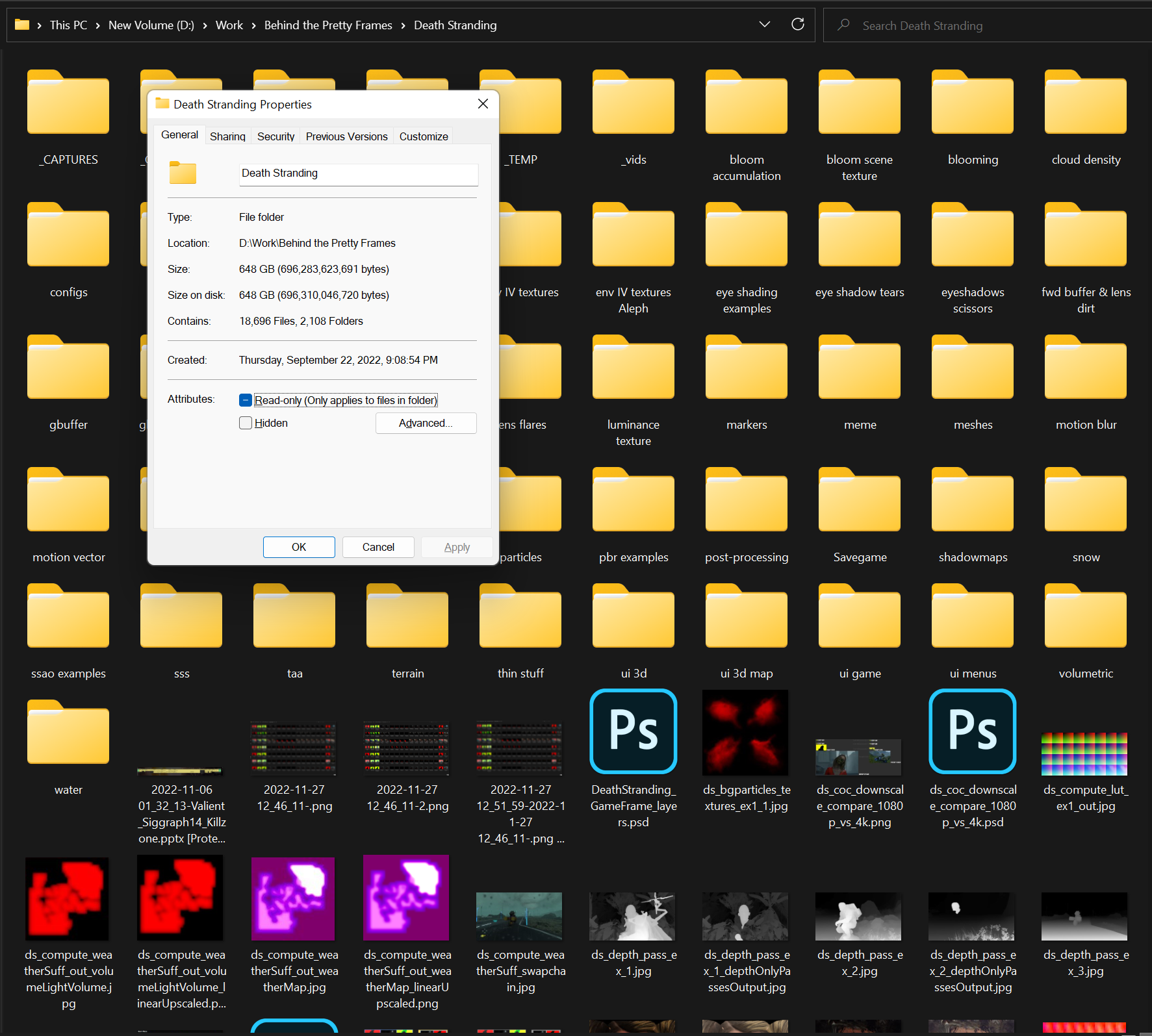
Related Readings & Videos
Developers, don’t mock people for being amazed by game dev techniques
Here’s what’s happening in Horizon: Zero Dawn every time you move a camera
PRACTICAL OCCLUSION CULLING IN KILLZONE 3
PRACTICAL OCCLUSION CULLING ON PS3
REFLECTIONS AND VOLUMETRICS OF KILLZONE SHADOW FALL
The Real-time Volumetric Cloudscapes of Horizon: Zero Dawn
REAL-TIME LIVE – SIGGRAPH 2022 – Decima presentation
GPU Gems 3 – Chapter 14. Advanced Techniques for Realistic Real-Time Skin Rendering
Yee et al. [2001] – Spatiotemporal sensitivity and visual attention for efficient rendering of dynamic environments
Spatiotemporal Sensitivity and Visual Attention for Efficient Rendering of Dynamic Environments
Disney Research – Irradiance Caching and Derived Methods (Chapter 3)
Selective Parallel Rendering for High-Fidelity Graphics
A Uniform Sky Illumination Model to Enhance Shading of Terrain and Urban Areas
General Sky Models for Illuminating Terrains
Learn OpenGL – Frustum Culling
An Introduction to Hybrid Log-Gamma HDR
Evil Boris – Death Stranding HDR settings and a brief overview of my findings
Filmic Tonemapping Operators
CG Cinematography – Chapter 1: Color Management
-m